
Controlling a current drawn from an adapter by a computer system

a technology of computer system and current draw, which is applied in the direction of liquid/fluent solid measurement, safety/protection circuit, instruments, etc., can solve the problems of slow response time relative, preventing the computer system from using the full output capabilities of the adapter, and requiring power temporarily exceeding the rated output power of the laptop adapter

Inactive Publication Date: 2013-08-29
APPLE INC
View PDF6 Cites 5 Cited by
  • Summary
  • Abstract
  • Description
  • Claims
  • Application Information

AI Technical Summary

Benefits of technology

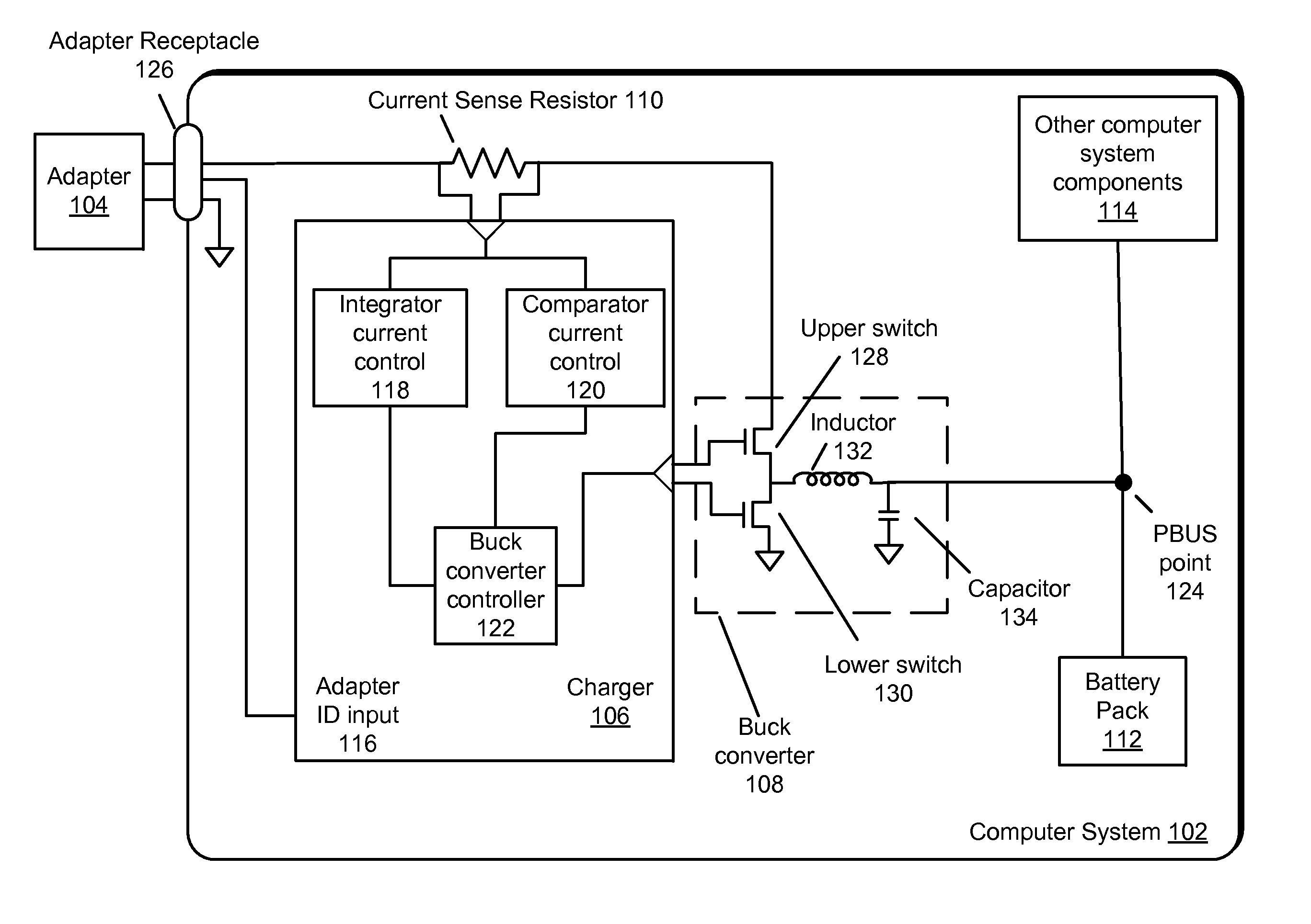
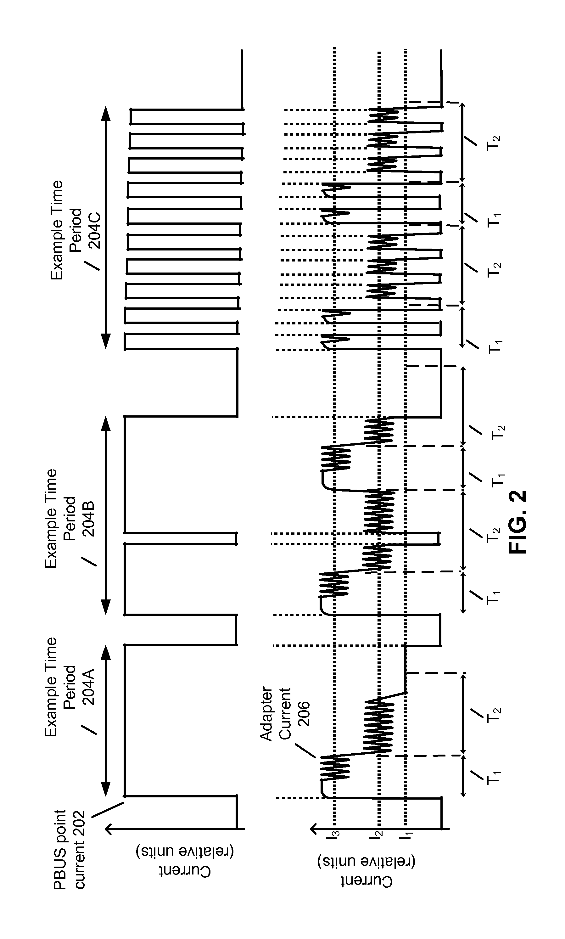
The present patent relates to techniques for controlling the current drawn from an adapter by a computer system. The technical problem addressed is the need to control the current drawn from the adapter to prevent damage to the computer system and to enable the computer system to use the full power capabilities of the adapter. Existing solutions such as integrators and comparators have slow response times, and using a faster control loop may not achieve the desired steady-state value. The invention proposes a new approach to address this problem.

Problems solved by technology

When these chips enter a high power demand state, the required power may temporarily exceed the rated output power of the laptop adapter.
Typically, the current drawn from the adapter by the computer system is controlled with a current control loop that uses an integrator which, due to the accuracy required, often has a slow response time relative to the speed at which the chips can increase their current demands.
Due to this relatively slow response time, the set point of the current control loop may have to be lowered from the rated output power of the adapter, preventing the computer system from using the full output capabilities of the adapter.
Furthermore, a faster current control loop such as one using a comparator typically cannot achieve the necessary accuracy to regulate the current drawn from the adapter to a desired steady-state value.
Additionally, using a faster control loop to regulate the current from the adapter to the steady-state value may prevent the full current output capabilities of the adapter from being used.

Method used


Image

  • Controlling a current drawn from an adapter by a computer system
  • Controlling a current drawn from an adapter by a computer system
  • Controlling a current drawn from an adapter by a computer system

Examples


Embodiment Construction

[0015]The following description is presented to enable any person skilled in the art to make and use the embodiments, and is provided in the context of a particular application and its requirements. Various modifications to the disclosed embodiments will be readily apparent to those skilled in the art, and the general principles defined herein may be applied to other embodiments and applications without departing from the spirit and scope of the present disclosure. Thus, the present invention is not limited to the embodiments shown, but is to be accorded the widest scope consistent with the principles and features disclosed herein.

[0016]The data structures and code described in this detailed description are typically stored on a computer-readable storage medium, which may be any device or medium that can store code and / or data for use by a computer system. The computer-readable storage medium includes, but is not limited to, volatile memory, non-volatile memory, magnetic and optical...


PUM


Abstract

The disclosed embodiments provide an apparatus that controls a current drawn from an adapter by a computer system. During operation, the apparatus senses the current drawn from the adapter using a first current sensor and a second current sensor, wherein a response time of the first current sensor is faster than a response time of the second current sensor. Then, when the current sensed using the first current sensor exceeds a predetermined high-current threshold, the apparatus limits the current drawn from the adapter to a first predetermined current limit. Additionally, when the current sensed using the second current sensor exceeds a predetermined thermal-limit current, the apparatus limits the current drawn from the adapter to the predetermined thermal-limit current.

Description

RELATED APPLICATION[0001]This application claims priority to U.S. Provisional Application No. 61 / 603,863, Attorney Docket Number APL-P13468USP1, entitled “Controlling a Current Drawn from an Adapter by a Computer System,” by inventors Mao Ye, Bharatkumar K. Patel, Kisun Lee, Manisha P. Pandya and Shimon Elkayam, filed 27 Feb. 2012, the contents of which are incorporated herein by reference.BACKGROUND[0002]1. Field[0003]The present embodiments relate to techniques for controlling a current drawn from an adapter. More specifically, the present embodiments relate to techniques for controlling a current drawn from an adapter by a computer system.[0004]2. Related Art[0005]Computer systems such as laptop computers are increasingly being manufactured with chips capable of substantially raising their power demands for short periods of time (e.g., by entering a “turbo” mode). When these chips enter a high power demand state, the required power may temporarily exceed the rated output power of...

Claims


Application Information

Patent Timeline
IPC IPC(8): G06F1/32
CPCG06F1/26G06F1/28G06F1/32H02J7/00304H02J7/007192H02J2207/40G06F1/20G06F1/263
Inventor YE, MAOPATEL, BHARATKUMAR K.LEE, KISUNPANDYA, MANISHA P.ELKAYAM, SHIMON
Owner APPLE INC
Learn More