Dscope aiming device

a aiming device and dscope technology, applied in the field of aiming devices, can solve the problems of rare survival in the marketplace of dscopes, and achieve the effect of simple and easy-to-use aiming devices

Inactive Publication Date: 2013-09-05
MILLETT JAMES ALLEN
View PDF3 Cites 22 Cited by
  • Summary
  • Abstract
  • Description
  • Claims
  • Application Information

AI Technical Summary

Benefits of technology

[0011]As described above, the instant invention provides a durable aiming device with no visible external controls. All ballistic calculations necessary for long-range shooting are performed automatically in relation to internal sensors and settings performed by tilting the weapon; thereby, rendering a simple and easy to use aiming device.

Problems solved by technology

There are numerous “Optical solutions” to the “Automatic Firing solution” problem sited in previous patents; however, few seldom survive in the marketplace because of the high cost of automatically moving optical components and the difficulty of maintaining accuracy with repeated impact from a weapon.

Method used


Image

  • Dscope aiming device
  • Dscope aiming device
  • Dscope aiming device

Examples


Embodiment Construction

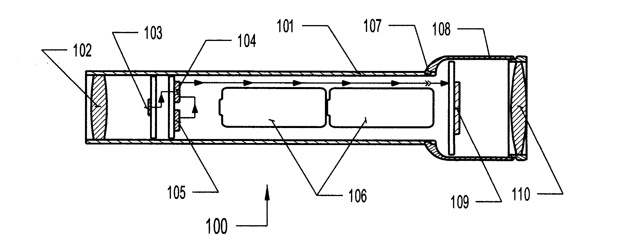
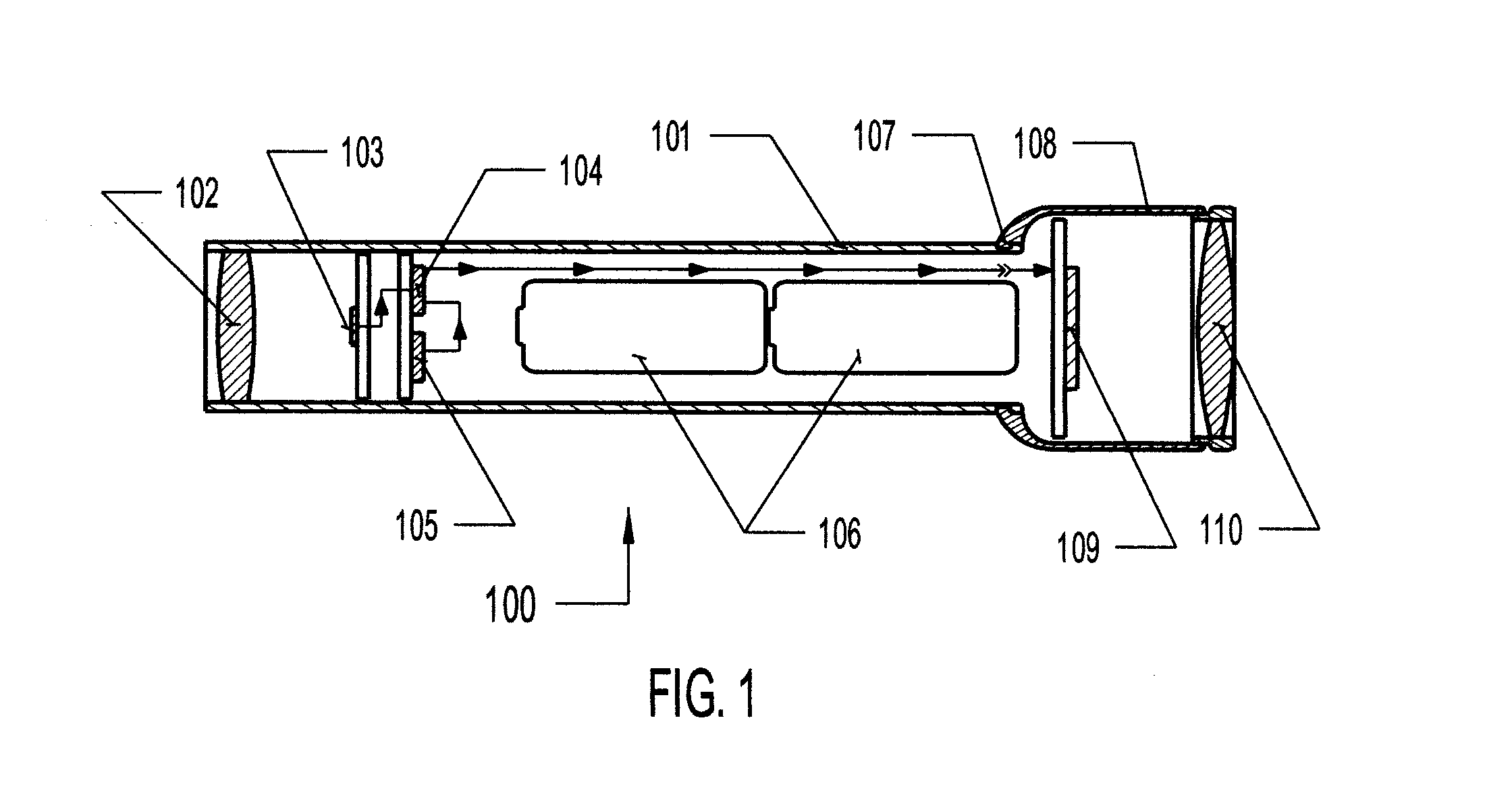
[0014]Referring now to FIG. 1, there is shown a representative cutaway schematic view of one embodiment of the aiming system 100 of the instant invention. Of course other configurations can be utilized depending on the actual use of the aiming device, e.g. with a rifle, with a hand gun, or other types of devices that need to be manually aimed.

[0015]The system (or device) shown in FIG. 1 includes an elongated tubular housing 101, typically, but not limitatively fabricated from anodized aluminum or the like. The housing 101 provides: the means to mount the front lens 102 and an enclosure for, the image sensor 103, the image processor 104 and its associated components, and the batteries 106 that provide power to the system. The housing 101 may also include an integral mounting system (not shown) for the purpose of mounting the aiming device 100 to the weapon upon which it will be used. The front lens 102 is mounted so as to focus light from the object at which the device is aimed onto ...


PUM


Abstract

An improved electronic aiming device for use with a weapon or other manually aimed device. Means are provided to vary the field of view, determine range to target, compensate for bullet drop, and to compensate for crosswind, without removing either hand from the weapon, by monitoring the tilt of the weapon upon which the device is mounted.

Description

BACKGROUND OF THE INVENTION[0001]1. Field of the Invention[0002]This invention is directed to aiming devises, in general, and to aiming devices with electronically enhanced target acquisition capabilities, in particular.[0003]2. Prior Art[0004]When making a long range shot with a firearm, the shooter must first determine a firing solution based on distance to target (Range), bullet drop due to the flight characteristic of the bullet and gravity (Drop), and crosswind component of the wind that is blowing at the time of firing (Windage).[0005]Typically, the shooter will have a chart taped to the side of his weapon, or will have memorized the values for each of the corrections i.e. Drop and Windage at various Ranges and wind velocities. The shooter must then make a correction for each of these component values. Two methods are commonly used for this purpose. The first is to manually adjust the turrets on an optical aiming device so that the reticule is directing the shooter to the corr...

Claims


Application Information

Patent Timeline
Patent Type & Authority Applications(United States)
IPC IPC(8): G06F19/00
CPCF41G1/38F41G1/44F41G1/00F41G1/473F41G3/06F41G3/165
Inventor MILLETT, JAMES ALLEN
Owner MILLETT JAMES ALLEN
Why Eureka
Try Eureka