Device and method for measuring temperature using infrared array sensors

a technology of infrared array and temperature measurement, which is applied in the field of thermal pictures, can solve the problems of serious errors in detecting temperature and/or thermal distribution from subjects, inconvenient use, and inability to detect a material or human body standing without movement, so as to improve the reliability of measuring temperature and thermal distribution, improve the accuracy of measurement, and facilitate use

Inactive Publication Date: 2013-09-05
EASYTEM
View PDF6 Cites 40 Cited by
  • Summary
  • Abstract
  • Description
  • Claims
  • Application Information

AI Technical Summary

Benefits of technology

[0034]According to the device and method of the present invention, for example, temperature at a specific part on an subject is measured through an infrared sensor module, after displaying an indicator corresponding to the specific part of the subject to be detected in temperature, when a picture of the specific part on the subject overlaps with an indicator. Therefore, temperature can be detected at the optimum condition of distance and angle to the subject, achieving more accurate measurement.
[0035]In addition, it is permissible to sort valid pixels to a target point of a subject to be detected and measure accurate temperature from the target point on basis of the valid pixel selection. For instance, a user is able to select a specific part of a person, e.g. forehead, ear, hand, etc., and measures temperature from the specific part more conveniently and exactly, enhancing reliability of measuring temperature and thermal distribution as well as easiness on use.
[0036]Furthermore, it is possible to calculate the ambient temperature value from invalid pixels around valid pixels and then correct an infrared sensor's own value with reference to the ambient temperature value. This enables more accurate correction than the conventional that just calculate an ambient temperature value by an internal temperature sensor, hence further raising reliability for a result of thermal detection.

Problems solved by technology

However, pyroelectric sensor 10 is disadvantageous upon which it is impossible to detect a material or human body standing without movement because it does not further generate any electric signal if infrared rays are continuously incident thereon.
However, in detecting thermal conditions only from specific parts of human body (e.g. forehead, ear, hand, or another part in human body) by means of the aforementioned thermal picture measurement units, it could be inconvenient on use because it is necessary to carefully adjust a distance and angle between a subject's part and the thermal picture measurement unit.
If a distance and angle for measurement is unsuitably adjusted, it will result in a serious error in detecting temperature and / or thermal distribution from a subject.
Especially, since only one sensor was used for measuring its own temperature, it could be inevitable to result in lower accuracy on thermal detection.
Such one-pixel information cannot provide any way of finding out an actual distance from a subject to be detected.
Moreover, the prior non-contacting measurement is incapable of detecting or correcting a shake or movement of a thermometer or subject, the reason of which is caused from that thermal data only by one pixel is insufficient to differentiate a subject's motion from a thermal variation.
Consequently, the former technologies just provide means for scanning a forehead and the around thereof, being insufficient to scan and detect temperature from the whole face, so that it is difficult to exactly detect temperature from a person who has higher temperature at other facial points rather than his forehead.

Method used


Image

  • Device and method for measuring temperature using infrared array sensors
  • Device and method for measuring temperature using infrared array sensors
  • Device and method for measuring temperature using infrared array sensors

Examples


Embodiment Construction

[0055]Hereinafter, various exemplary embodiments about a device and method for measuring temperature with infrared array sensor will now be described more fully with reference to the accompanying drawings.

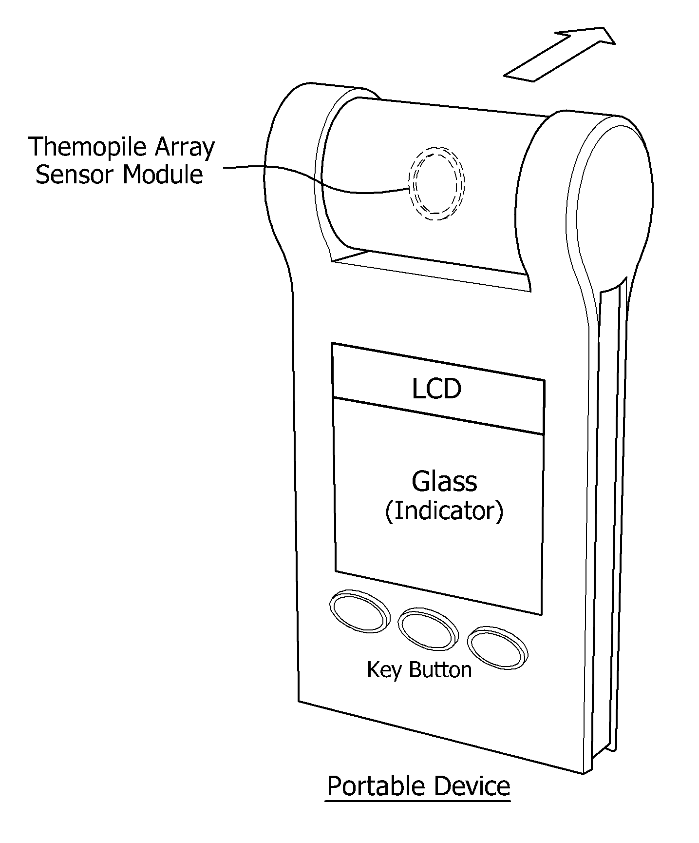
[0056]A device for measuring temperature with infrared array sensor may be configured by exemplarily including an infrared array sensor module, a camera module, and an electric circuit module controlling the other componential modules. In the configuration, the infrared array sensor module may be formed of a plurality of infrared sensors (e.g. thermopile sensors) as like a thermopile array sensor. The infrared sensors are arranged in an pixel array, each corresponding to each pixel, to acquire thermal picture information from a subject such as material or human body. The camera module is used for obtaining image information from a subject, including a camera device such as charge-coupled device (CCD) or complementary metal-oxide-semiconductor (CMOS) camera. In the mean time, as ill...


PUM

PropertyMeasurementUnit
timeaaaaaaaaaa
temperatureaaaaaaaaaa

Abstract

Disclosed is a device and method for measuring temperature with infrared array sensor. This device includes: an infrared array sensor module to take thermal picture information of a subject, including a plurality of infrared sensors arranged in an array of pixels; an on-screen display module to generate an indicator having a profile corresponding to an entire or local shape of the subject and defining a target point to be measured for temperature; a display module to express the indicator and the thermal picture information; and a controller to enable the infrared array sensor module to measure the subject's temperature if the target point displayed by the thermal picture information overlaps with the indicator while the thermal picture information is expressed on the display module along with the indicator.

Description

BACKGROUND[0001]1. Technical Field[0002]The present invention relates generally to measurement for thermal pictures corresponding to infrared rays arising from subjects such as material or human bodies. In particular, this invention is concerned with a device for measuring temperature of a subject with an infrared array sensor capable of detecting a thermal picture from the subject, and a method for measuring temperature the subject entirely or locally by means of the device.[0003]2. Related Art[0004]Nowadays in various technical fields are widely being used thermal detection devices for sensing temperature from material or human bodies in response to even minute infrared rays.[0005]For instance, a thermal detection device automatically turning on / off a lamp at gloomy spot and others, as shown in FIG. 1, is composed including pyroelectric sensor 10, amplifier (AMP) 11, low pass filter (LPF) 12, comparator 13, timer 14, driver 15, lamp 16 and light sensor 17.[0006]In such a thermal d...

Claims


Application Information

Patent Timeline
Patent Type & Authority Applications(United States)
IPC IPC(8): G01K1/20
CPCG01J5/0025G01J5/025G01J5/0265G01J5/089G01J2005/0081G01J5/0859A61B5/01G01K1/20G01J2005/106G01J2005/0077G01J5/0275A61B5/70A61B5/743G01J5/60G01J5/48G01J5/07G01J5/02
Inventor SHIN, JAE-WOO
Owner EASYTEM
Why Eureka
Try Eureka