Reinforcement bar coupler

a technology of reinforcement bars and couplers, which is applied in the direction of couplings, manufacturing tools, mechanical instruments, etc., can solve the problems of large portion of reinforcement bars lost, increased working time, and easy detachment of reinforcement bars, so as to increase the diameter of the clamping spring, easy connection, and increase the diameter

Inactive Publication Date: 2013-09-05
ROC CO LTD
View PDF11 Cites 14 Cited by
  • Summary
  • Abstract
  • Description
  • Claims
  • Application Information

AI Technical Summary

Benefits of technology

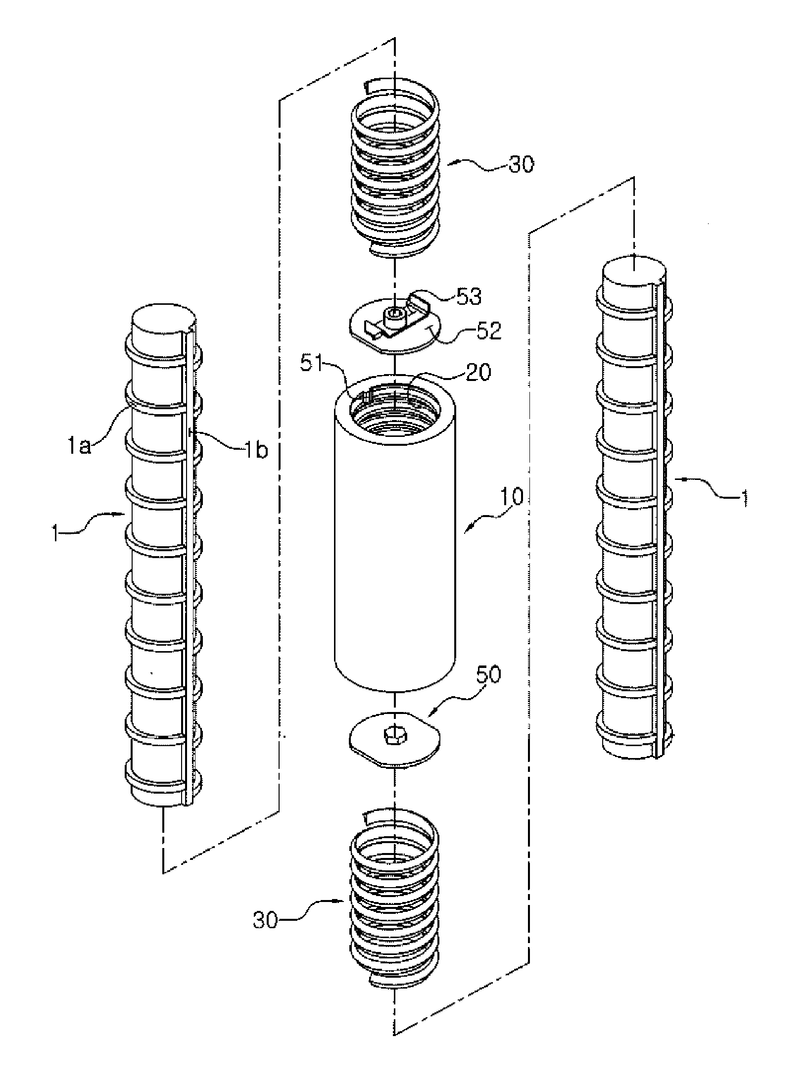
[0019]The reinforcement bar coupler according to the present invention is characterized by further including a one-touch connecting means which prevents the clamping spring from interfering with insertion of the reinforcement bar while the reinforcement bar is being inserted into the coupler cap, and causes the clamping spring to hold the reinforcement bar when the insertion of the reinforcement bar into the coupler cap is completed. The one-touch connecting means includes a hook portion provided adjacent to the outer end of the coupler cap. The hook portion supporting one end of the clamping spring, a support plate provided inside the coupler cap, and a leaf spring supported by the support plate, the leaf spring having a protrusion protruding from the support plate between the hook portion and the leaf spring such that the other end of the clamping spring is supported in a state in which the clamping spring is twisted in a direction in which the diameter there is increased. When the reinforcement bar is inserted into the coupler cap and presses against the protrusion, the protrusion is recessed due to elasticity and no longer supports the other end of the clamping spring, so that the diameter of the clamping spring is restored due to elasticity.
[0020]According to the reinforcement bar coupler of the present invention having the above-described configurations, it is possible to easily connect and couple reinforcement bars with one touch based on a change in the diameter of the clamping springs caused by twisting using a relatively simple configuration. Since the bottom and the inclined taper plane are formed without machining the female thread, it is easy to machine and manufacture the reinforcement bar coupler. Since the cross-section of the clamping spring has a triangular shape, the reinforcement bar can be more securely fixed based on the sliding movement of the clamping spring and the thrust of the angled end portions into the reinforcement bar. Since the one-touch connecting means allows the clamping spring to be fitted into and fastened to the base spring in the state in which the clamping spring is twisted in the direction in which its diameter is increased and the diameter of the clamping spring to be restored when the insertion of the reinforcement bar is completed, the reinforcement bars can be properly coupled to each other irrespective the difference even if there is a difference in the diameter between reinforcement bars due to characteristics of the manufacturing process of the reinforcement bars.

Problems solved by technology

A large portion of the reinforcement bars are lost, and the reinforcement bars are easily detached due to the weak strength of jointed portions.
Also, a working time is increased due to poor constructability, which is problematic.
The welding has problems in that construction is difficult and the strength of the portions of the reinforcement bars adjacent to the welded portions is remarkably weakened because of the heat generated when the welded portions are heated.
Accordingly, a long time and a large cost are spent on construction.
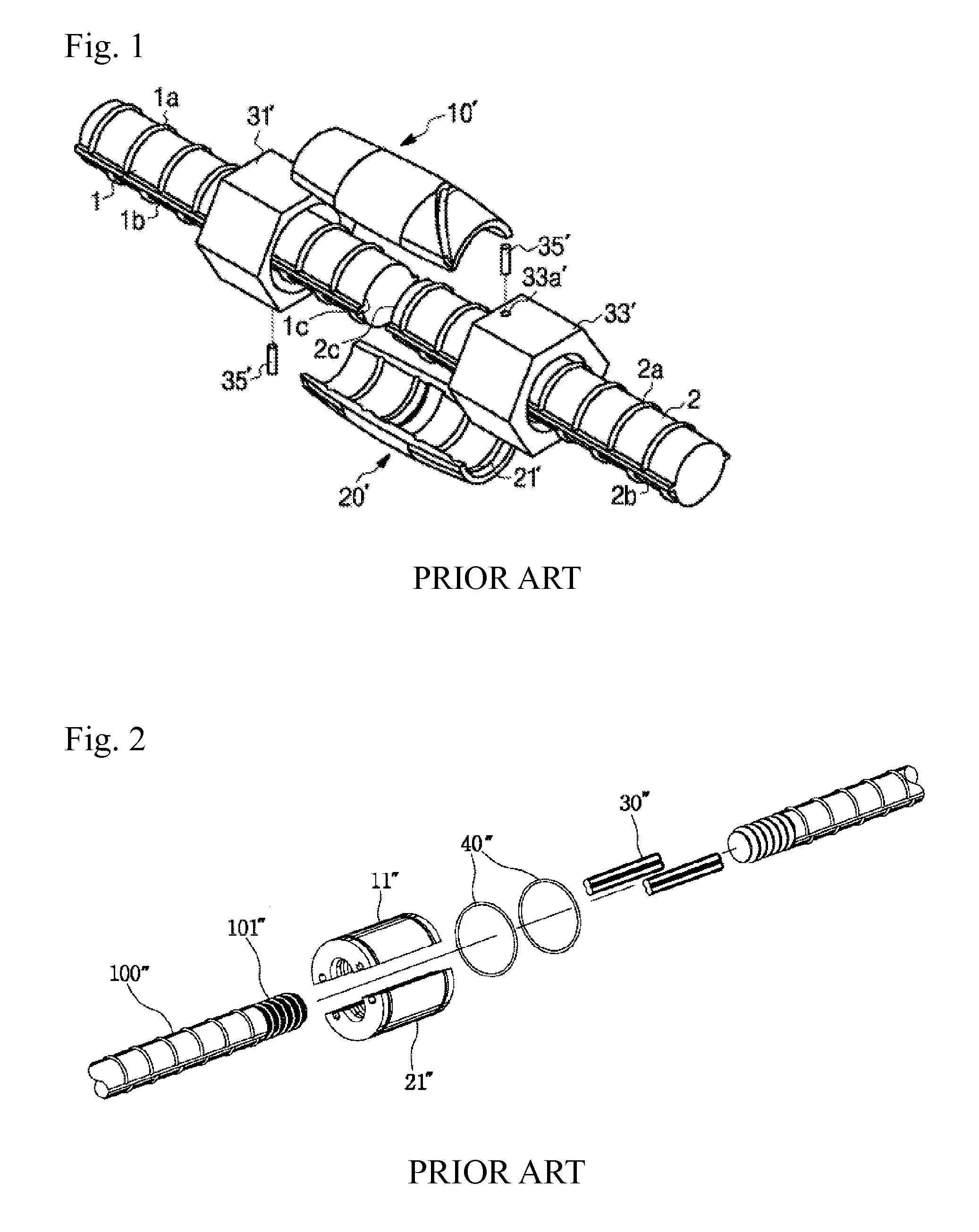
However, this approach of the related art has a significant drawback in that ends of the reinforcement bars 100″, which are manufactured at standardized sizes, must be machined before use in order to form the connecting portions 101″.
In addition, the coupler members 11″ and 21″, the coupler connecting pins 30″, the rubber bands 40″ and the like must be individually and manually fastened to the reinforcement bars 100″, thereby leading to the problems of increased construction time and cost.

Method used


Image

  • Reinforcement bar coupler
  • Reinforcement bar coupler
  • Reinforcement bar coupler

Examples


first embodiment

[0031]Referring to the figures, the reinforcement bar coupler according to the present invention includes a coupler cap 10, female threads 20, a clamping spring 30 and one-touch connecting means 50.

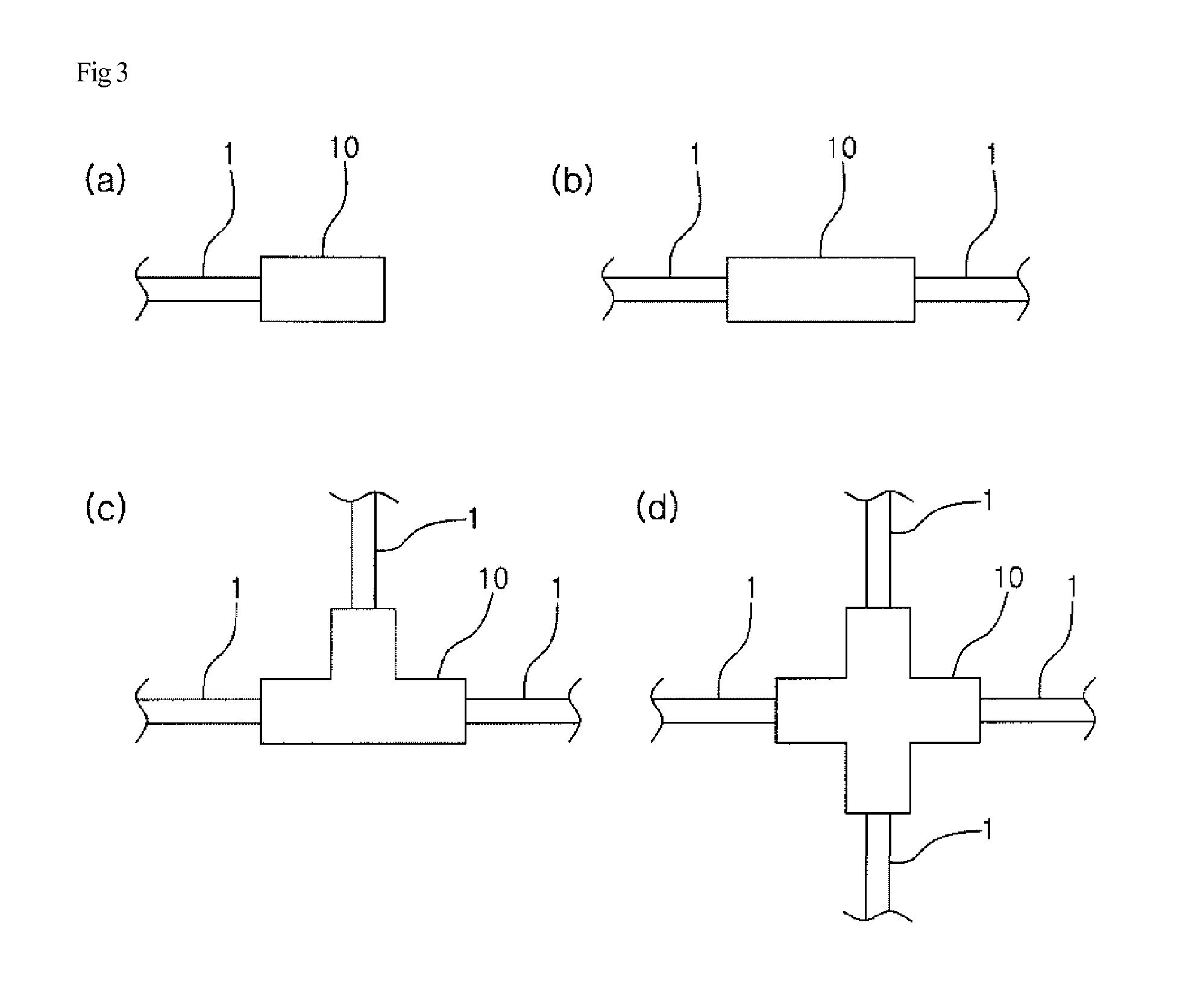
[0032]The coupler cap 10 is configured such that the reinforcement bars 1 which are to be connected and fixed to each other are inserted into the coupler cap 10 through the open outer ends. As shown in FIG. 3, the coupler cap 10 may have a variety of shapes, such as (a) an anchor type, (b) a linear type, (c) a T type, (d) a cross type, and so on.

[0033]As shown in the figures, each of the reinforcement bars 1 which are referred to herein may include a reinforcement bar having a typical shape in which the joint protrusions 1a and the rib protrusions 1b are formed, as well as a bolt having a male thread on the outer circumference thereof and a bar type member having a predetermined length.

[0034]According to the first embodiment of the present invention, the coupler cap 10 is illustrated as a...

second embodiment

[0043]The one-touch connecting means 50 prevent the clamping springs 30 from interfering with the insertion of the reinforcement bars 1 in the process in which the reinforcement bars 1 are being inserted into the coupler cap 10. When the insertion of the reinforcement bars 1 into the coupler cap 10 is completed, the one-touch connecting means 50 allow the clamping spring 30 to hold the reinforcement bars 1. Each of the one-touch connecting means 50 includes a hook portion 51, a support plate 52 and a leaf spring 53. A detailed description thereof will be given with respect to the present invention which will be described later.

[0044]The reinforcement bar coupler according to the first embodiment of the present invention has been described hereinabove, and a detailed description will be given below of a reinforcement bar coupler according to the second embodiment of the present invention.

[0045]FIG. 6 is an exploded perspective view showing the reinforcement bar coupler according to t...


PUM


Abstract

A reinforcement bar coupler, in which a female thread having an inclined taper plane is formed on the inner surface of a coupler cap, and a clamping spring is inserted into and fastened to the female thread. When a reinforcement bar is inserted into the clamping spring, the clamping spring is closely abutted to the bottom of the female thread and is increased in diameter so that the reinforcement bar slips. With the reinforcement bar being inserted, when an external force is applied in the direction opposite to the direction in which the reinforcement bar is inserted, the clamping spring moves along the inclined taper plane and is decreased in diameter, thereby holding the reinforcement bar. It is therefore possible to easily connect and couple the reinforcement bar with one touch based on a change in the diameter of the clamping spring using a relatively simple configuration.

Description

CROSS REFERENCE TO RELATED APPLICATIONS AND CLAIM OF PRIORITY[0001]This patent application is a National Phase application under 35 U.S.C. §371 of International Application No. PCT / KR2011 / 008203, filed Oct. 31, 2011, which claims priority to Korean Patent Application Nos. 10-2010-0109388 filed Nov. 4, 2010, and 10-2011-0007910 filed Jan. 26, 2011, entire contents of which are incorporated herein by reference.BACKGROUND[0002]1. Technical Field[0003]The present invention relates to a reinforcement bar coupler.[0004]2. Background Art[0005]In general, a reinforcement bar is used a manner in which it is buried inside concrete when constructing a steel-reinforced concrete structure in order to reinforce the strength of the concrete structure. In particular, a large number of reinforcement bars are used for reinforcement in large buildings, special structures, and engineering work structures such as bridges.[0006]However, since reinforcement bars are manufactured to be standardized regular...

Claims


Application Information

Patent Timeline
Patent Type & Authority Applications(United States)
IPC IPC(8): E04C5/16
CPCE04C5/165E04C5/166Y10T403/602F16B21/205E04C5/162
Inventor KIM, BYUNG SUBHONG, MAN KI
Owner ROC CO LTD
Why Eureka
Try Eureka