Ureteral calculus suction instrument having a shaft

a technology of ureteral calculus and suction shaft, which is applied in the field of ureteral calculus suction instruments, can solve the problems of difficult to hold the distal opening of the suction channel, blockage, and the suction of calculus fragments through the suction channel, and achieve the effect of reliable steering and control

Active Publication Date: 2013-09-05
OLYMPUS WINTER & IBE
View PDF22 Cites 16 Cited by
  • Summary
  • Abstract
  • Description
  • Claims
  • Application Information

AI Technical Summary

Benefits of technology

[0016]The ureteral calculus suction instrument may exhibit as the shaft only the hose, which can also be formed as a rigid tube, in order to allow for reliable steering and control when pushed forwards into the body. Advantageously, however, according to claim 9, the ureteral calculus suction instrument is formed as a ureteroscope. This provides a range of advantages, such as, for example, the optical system provided in the ureteroscope, which allows for suction extraction to take place under visual monitoring and control.

Problems solved by technology

A disadvantage with the known generic ureteral calculus suction instruments is the suction of calculus fragments through the suction channel, which is very narrow, with a cross-section in the size range of the calculus fragments, as a result of which blockages occur due to calculus fragments becoming wedged in the suction channel.
If the collecting container is very soft, it may be difficult to hold its distal opening in a position which is favourable for the suction of calculus fragments.
Such measures, however, lead to a reduction in the suction capacity, which makes the suctioning of calculus fragments more difficult.

Method used


Image

  • Ureteral calculus suction instrument having a shaft
  • Ureteral calculus suction instrument having a shaft

Examples


Embodiment Construction

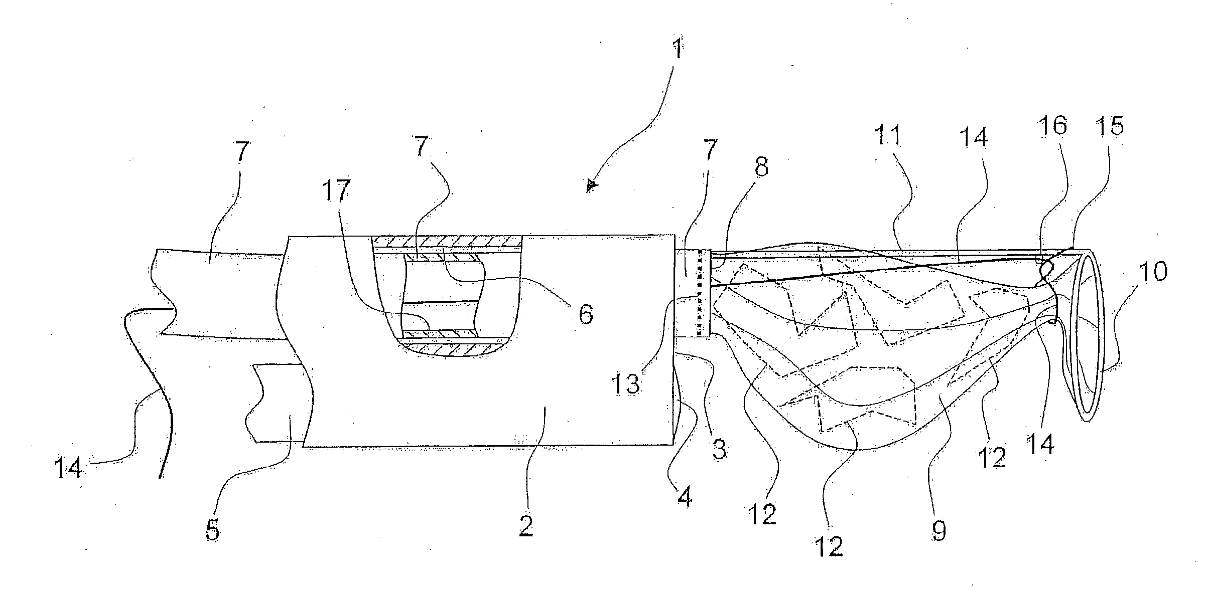
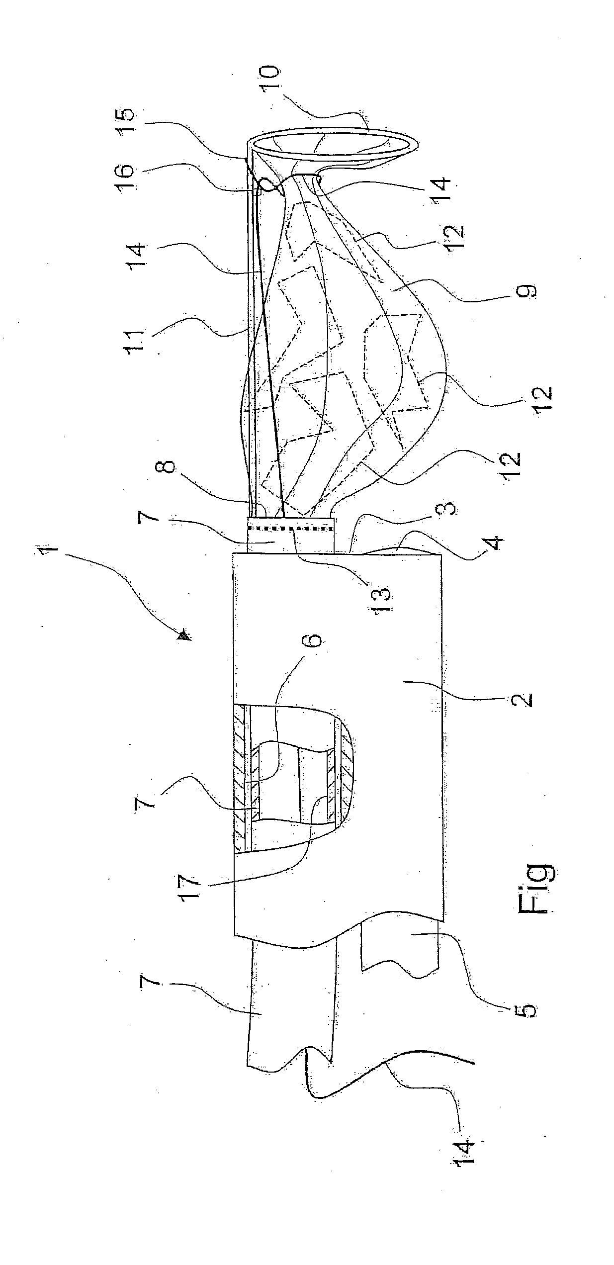
[0018]Represented in the FIGURE is a ureteral calculus suction instrument in the form of a ureteroscope 1, with only the distal end region of its shaft 2 represented. The shaft 2 ends distally with its distal face surface 3, in which a lens 4 of an optical system is located, which exhibits an image conductor 5 running through the shaft 2, which conveys the image acquired by the lens 4 to the proximal end of the shaft 2, in order to be observed or displayed there. The image conductor 5 can be designed as an arrangement of rod lenses or as a light-conducting fibre bundle. A camera can also be arranged at the lens 4, wherein the image conductor 5 is designed as a video cable.

[0019]In a sectional region of the shaft 2 it can be seen that a working channel 6 runs through this. In a usual arrangement this is open at both ends. In the embodiment shown, it accommodates a hose 7 with a lumen 17, which can be connected at the proximal end, not shown, to a suction device, such as a pump.

[0020]...


PUM


Abstract

A ureteral calculus suction instrument having a shaft through which a suction channel that can be connected to a suction device passes, wherein a collecting container having a distal opening and a proximal opening is arranged distally from the shaft, of which openings the proximal opening is connected to the distal end of the suction channel

Description

CROSS-REFERENCE TO RELATED APPLICATION[0001]The present application is based upon and claims the benefit of priority from PCT / EP2011 / 002465 filed on May 18, 2011, which claims benefit to DE 10 2010 024 360.4 filed on Jun. 18, 2010, the entire contents of each of which are incorporated herein by reference.BACKGROUND[0002]1. Field The present invention generally relates to a ureteral calculus suction instrument, and particularly to a ureteral calculus suction instrument of the type referred to in claim 1.[0003]2. Prior Art[0004]Ureteroscopes serve to work in the ureter, the channel within the body which connects the kidneys to the bladder. Because this channel is very narrow, the diameter of the shaft of the ureteroscope must not be more than a maximum of 4-5 mm.[0005]The very narrow cross-section of the shaft must accommodate the image conductor of an optical system. This exhibits at the distal end of the shaft a lens, from which an image conductor runs along the length of the shaft,...

Claims


Application Information

Patent Timeline
Patent Type & Authority Applications(United States)
IPC IPC(8): A61B17/22
CPCA61B1/00087A61B17/22A61B1/307A61B17/221A61B17/3207A61B19/5212A61B2017/0023A61B2017/00274A61B2017/00287A61B2017/22079A61B2017/2215A61B2018/00547A61B2217/005A61M1/008A61B1/015A61B90/361A61M1/84
Inventor CARROUX, ALEXANDER
Owner OLYMPUS WINTER & IBE
Why Eureka
Try Eureka