Range switching device

a technology of switching device and range, which is applied in the direction of transportation and packaging, mechanical equipment, propulsion parts, etc., can solve the problems of vehicle running in reverse and inability to design combinations, and achieve the effect of increasing safety

Active Publication Date: 2013-09-12
SUBARU CORP
View PDF32 Cites 7 Cited by
  • Summary
  • Abstract
  • Description
  • Claims
  • Application Information

AI Technical Summary

Benefits of technology

[0018]With such a configuration, where power supply is interrupted for any reason, the neutral range is assumed, thereby making it possible to increase safety further.

Problems solved by technology

However, with the technique described in JP-A No. 2008-128475, when switching between drive and reverse is performed using a drive / reverse switching valve, where a failure mode occurs such that the state of the valve is reversed, abrupt switching can take place from drive to reverse or from reverse to drive.
To resolve this problem, it is possible to increase the failsafe ability by detecting the failure state and creating different combinations of control states of a plurality of valves, but in this case where the failure detection speed is low, the designed combination is not obtained and the vehicle might run in reverse.

Method used


Image

  • Range switching device
  • Range switching device
  • Range switching device

Examples


embodiment 1

[0027]Embodiment 1 of a range switching device according to the present invention is explained below.

[0028]The range switching device of according to 1 is provided, for example, at a continuously variable transmission (CVT) that is installed on an automobile such as a passenger car and transmits the output of an engine.

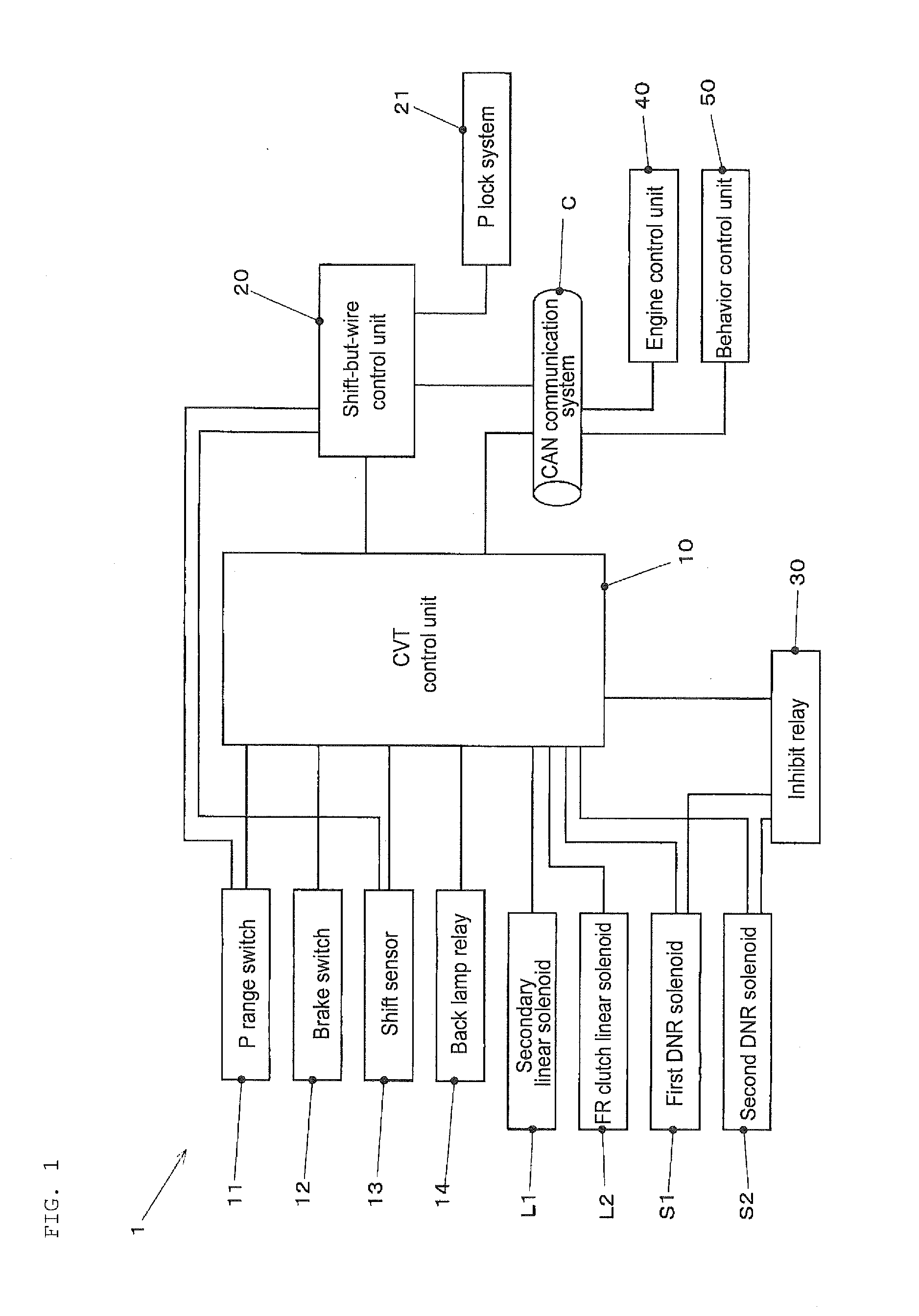
[0029]FIG. 1 is a schematic block diagram of a transmission control system including the range switching device of according to 1.

[0030]As shown in FIG. 1, a transmission control system 1 has a CVT control unit 10, a shift-by-wire control unit 20, and an inhibit relay 30 and controls a secondary linear solenoid L1, a FR clutch linear solenoid L2, a first DNR solenoid S1, and a second DNR solenoid S2.

[0031]The CVT control unit 10 performs integral control of the CVT and auxiliary device thereof and is constituted by an information processing device such as a CPU, a memory device such as a ROM or a RAM, an input / output interface, and a bus connecting the aforementioned ...

embodiment 2

[0110]Embodiment 2 of the range switching device according to the present invention is explained below.

[0111]In Embodiment 2, the components substantially identical to those of Embodiment 1 are assigned with the same reference numerals and the explanation thereof is herein omitted. Thus, mainly the differences between the examples are explained.

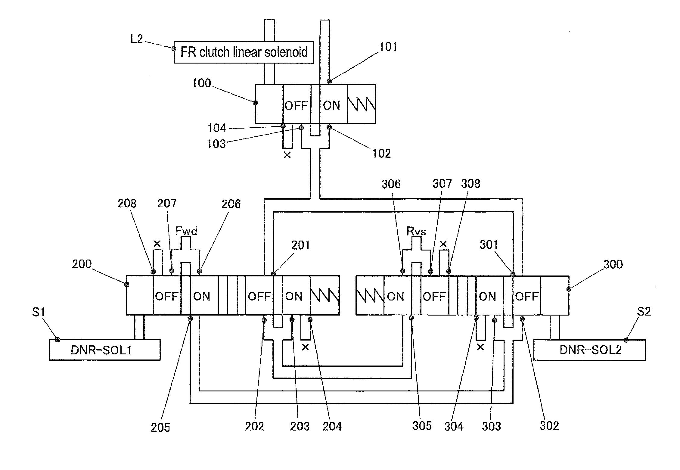
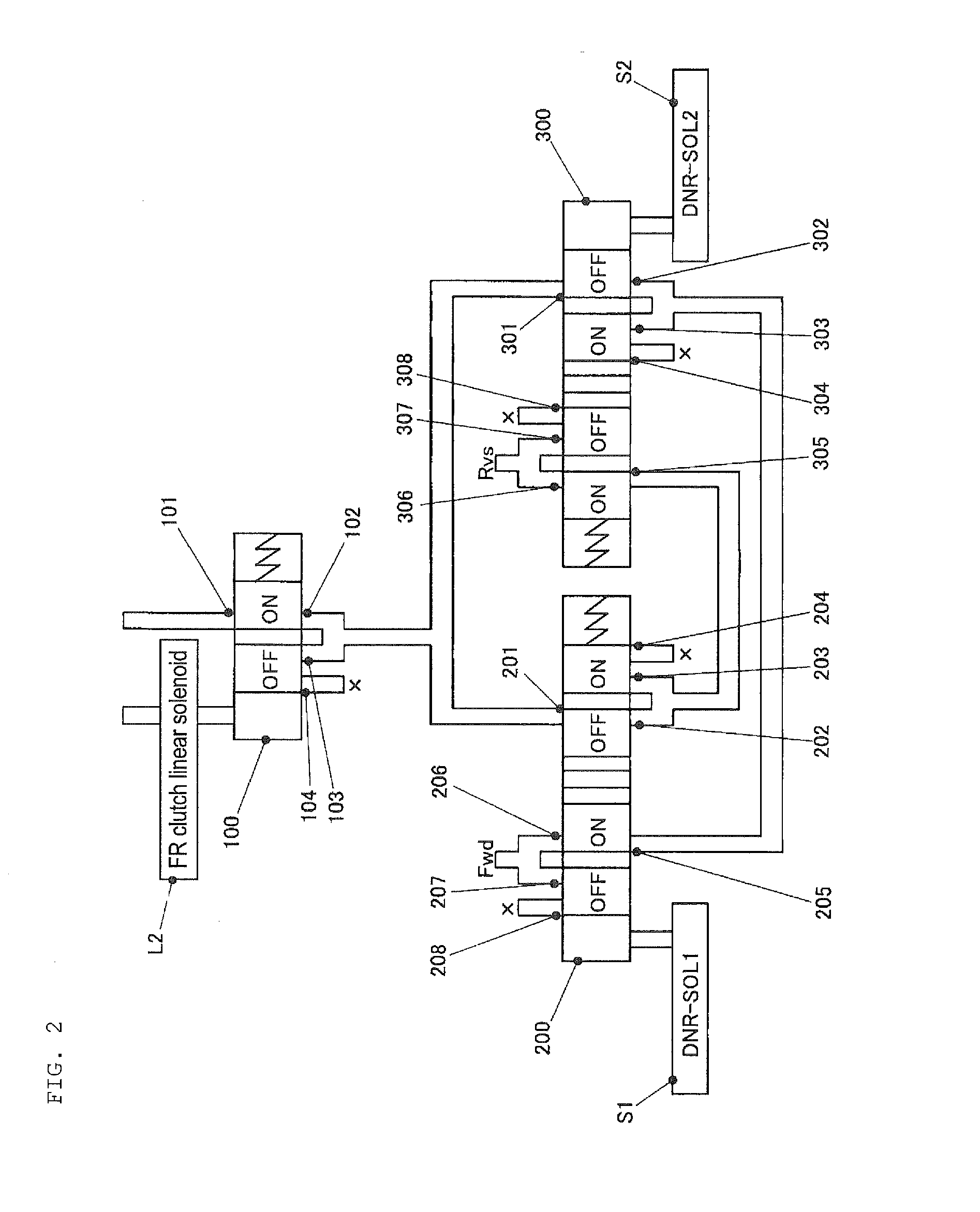
[0112]FIG. 7 shows the hydraulic circuit of the range switching device of Embodiment 2.

[0113]In Embodiment 2, the state of the spool valve 300 in relation to the ON / OFF switching of the second DNR solenoid S2 is reversed with respect to that of Example 1.

[0114]The effect substantially identical to that of the above-described Embodiment 1 can be also obtained in Example 2.


PUM


Abstract

Provided is a range switching device for performing switching among drive, reverse, and neutral ranges of a transmission. The device includes a first switching valve driven by a first actuator and a second switching valve driven by a second actuator. The valves switch an oil channel to transmit the oil pressure from an oil pressure supply source between first state and second states. When the first and second switching valves are in the first and second states respectively, the oil pressure is transmitted to the forward fastening element. When the first and second switching valves are in the second state and first states respectively, the oil pressure is transmitted to the reverse fastening element. When both the valves are in the first or second state, oil pressure transmission to the forward and reverse fastening elements is substantially blocked.

Description

CROSS-REFERENCE TO RELATED APPLICATIONS[0001]The present application claims priority from Japanese Patent Application No. 2012-051584 filed on Mar. 8, 2012, the entire contents of which are hereby incorporated by reference.BACKGROUND OF THE INVENTION[0002]1. Field of the Invention[0003]The present invention relates to range switching devices that perform switching among drive, reverse, and neutral ranges in an automatic transmission of a vehicle such as an automobile, and more particularly to a range switching device that prevents reverse running and ensures safety even in the case of a failure.[0004]2. Description of the Related Art[0005]In an automatic transmission such as a CVT or a planetary gear step AT provided in an automobile or the like, the drive, reverse, and neutral ranges are switched by controlling the oil pressure supplied to engagement elements such as a forward clutch and a reverse clutch.[0006]Switching among such drive, reverse, and neutral ranges has conventional...

Claims


Application Information

Patent Timeline
Patent Type & Authority Applications(United States)
IPC IPC(8): F16H59/08
CPCF16H61/0246F16H61/12F16H61/66Y10T74/20024F16H2061/1264F16H59/08F16H2061/1204
Inventor KINOSHITA, TAKAHIRO
Owner SUBARU CORP
Why Eureka
Try Eureka