Method and system for removing hydrocarbon deposits from heat exchanger tube bundles

a technology of hydrocarbon deposits and heat exchanger tubes, which is applied in the direction of cleaning heat exchange devices, flush cleaning, cleaning using liquids, etc., can solve the problems of reducing the effectiveness of the heat exchanger, requiring the operator to consume more energy to achieve the desired degree of temperature change, and requiring a shut-down of the plant's operation, so as to reduce the cleaning time of the bundles and reduce the amount of time , the effect of saving energy

Inactive Publication Date: 2013-09-12
T5 TECH
View PDF11 Cites 17 Cited by
  • Summary
  • Abstract
  • Description
  • Claims
  • Application Information

AI Technical Summary

Benefits of technology

[0008]The present invention comprises a method and system of cleaning a heat exchanger tube bundle so as to remove hydrocarbon deposits. Using embodiments of the present invention, bundle cleaning time may be reduced by as much as 800 percent over current methods, making the process more cost-effective by drastically

Problems solved by technology

During use, carbonaceous deposits including heavy oil, bitumen, and other hydrocarbons can form on the tube bundles, reducing the effectiveness of the heat exchanger and forcing the operator to consume more energy to achieve the desired degree of temperature change.
First, removal of the heat exchanger tube bundles from service typically requires a shut-down of the plant's operation.
As a result, the cleaning of heat exchanger tube bundles can lead to significant revenue losses for the plant operator.
In addition, current methods typically remove only about 80-85% of the hydrocarbon deposits from the heat exchanger tube bundles.
Thus, the

Method used


Image

  • Method and system for removing hydrocarbon deposits from heat exchanger tube bundles
  • Method and system for removing hydrocarbon deposits from heat exchanger tube bundles
  • Method and system for removing hydrocarbon deposits from heat exchanger tube bundles

Examples


Embodiment Construction

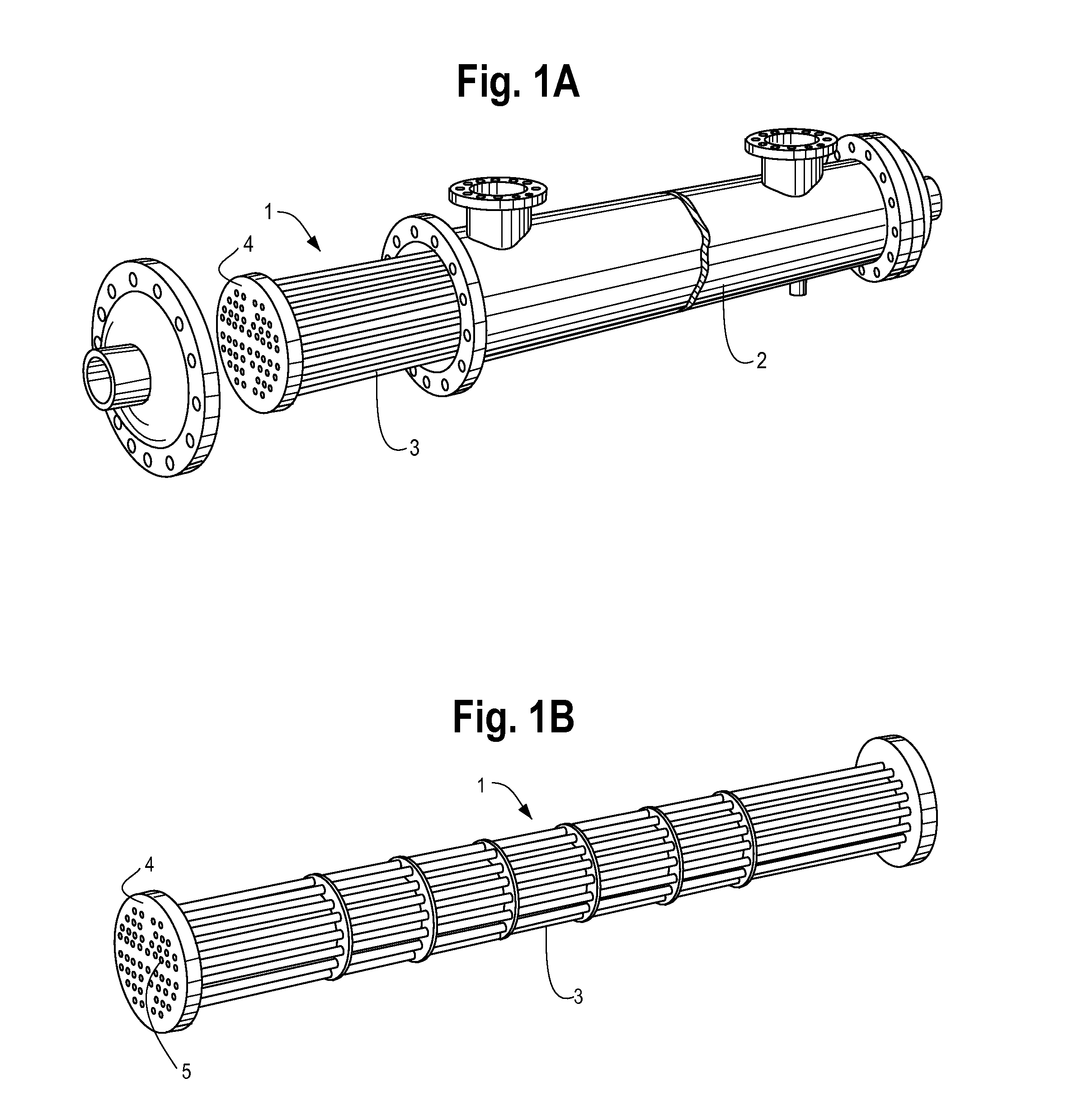
[0034]A heat exchanger tube bundle of the type that may be treated by the present invention is illustrated in FIG. 1. A heat exchanger tube bundle 1 is made up of a large number of individual tubes packed together to form a cylindrical structure. When in use, the heat exchanger tube bundle is surrounded by a shell 2. Accordingly, a heat exchanger tube bundle 1 comprises an exterior, or shell-side, surface 3 and a tube sheet surface 4. Heat exchanger bundles are often very large, typically ranging up to 84 inches in diameter and 30 feet in length. When used in certain industries, such as the gas and oil industry, heat exchanger tube bundles 1 become contaminated with hydrocarbon deposits, such as heavy oils, diluents, paraffins and / or bitumen.

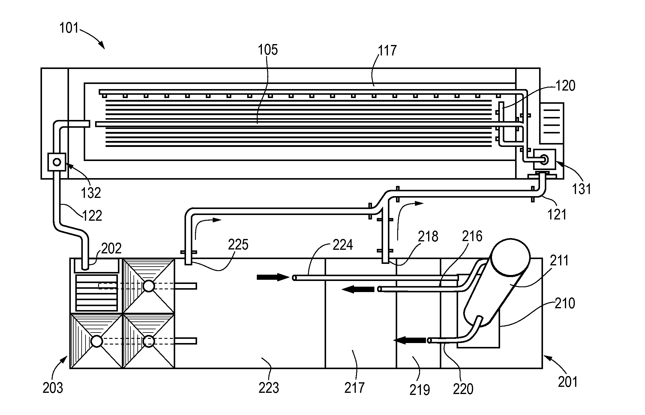
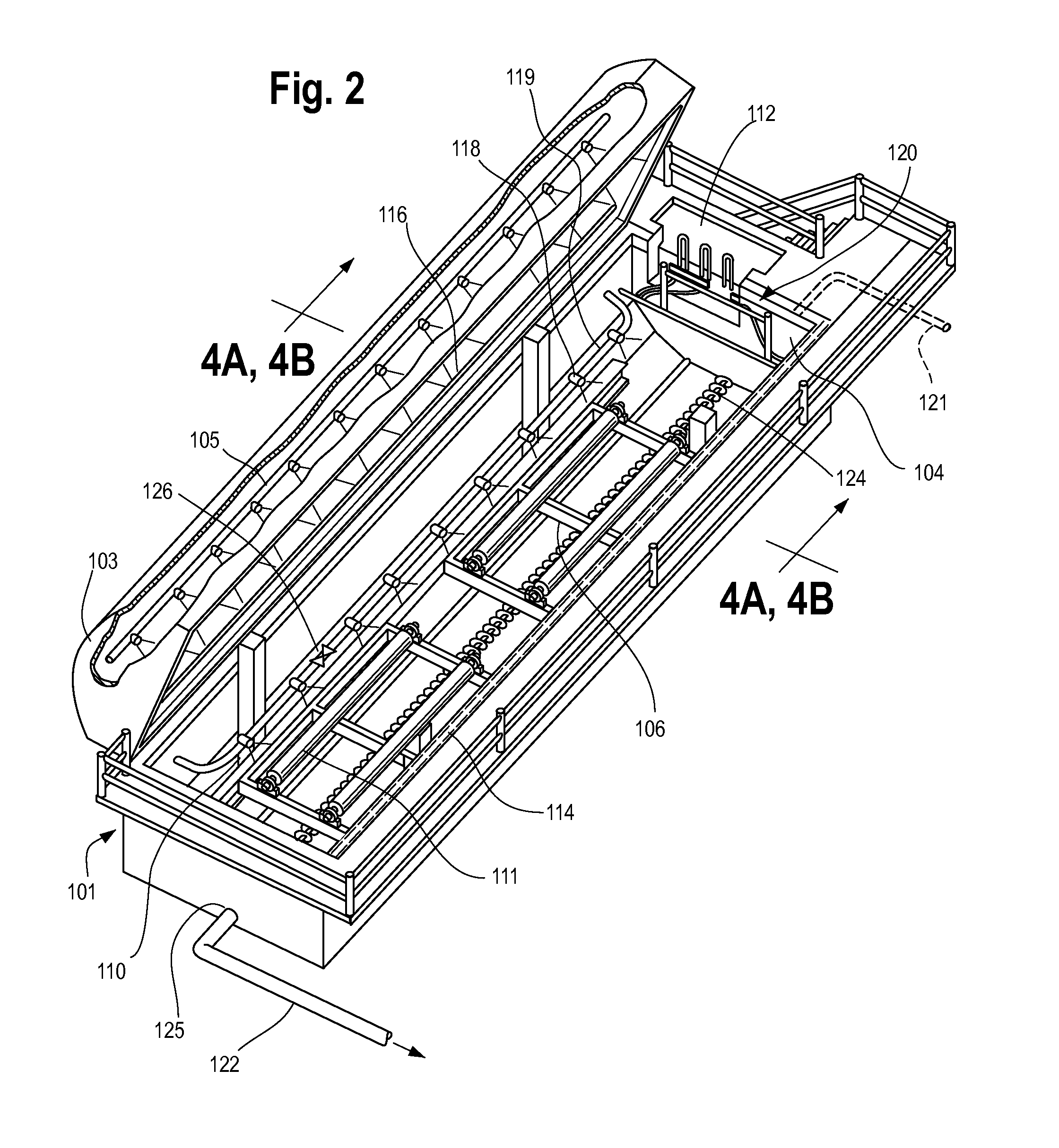
Heat Exchanger Tube Bundle Cleaning System

[0035]According to an aspect of the present invention, a system is provided for the removal of hydrocarbon deposits from a heat exchanger tube bundle by immersion in an organic solvent. A preferred embod...


PUM

PropertyMeasurementUnit
Fractionaaaaaaaaaa
Timeaaaaaaaaaa
Fractionaaaaaaaaaa

Abstract

A method and system for removing hydrocarbon deposits from a heat exchanger tube bundle using an organic solvent. After contact with a heat exchanger tube bundle, the contaminated organic solvent may be treated to remove solids, base waters, and/or suspended hydrocarbons, and then again contacted with a heat exchanger tube bundle for the removal of hydrocarbon deposits. This allows for the removal of hydrocarbon deposits from a heat exchanger tube bundle in an efficient and environmentally friendly manner. The treatment of the heat exchanger tube bundle is also preferably performed using a method and system by which, through contact of the heat exchanger tube bundle with an organic solvent, a large percentage of hydrocarbon deposits are removed from the heat exchanger tube bundle in a short period of time.

Description

BACKGROUND OF THE INVENTION[0001]1. Field of the Invention[0002]The present invention relates generally to a method and system for removing hydrocarbon deposits from heat exchanger tube bundles. More particularly, an aspect of the present invention relates to a method and system for thoroughly and efficiently cleaning heat exchanger tube bundles while minimizing the environmental impact of the cleaning process.[0003]2. Description of the Related Art[0004]Heat exchanger tubes bundles are used in chemical processes to either raise or lower the temperature of a fluid. They are heavily used in the oil and gas industry, such as by refineries, up-graders, and gas plants. During use, carbonaceous deposits including heavy oil, bitumen, and other hydrocarbons can form on the tube bundles, reducing the effectiveness of the heat exchanger and forcing the operator to consume more energy to achieve the desired degree of temperature change. Accordingly, in order to maintain an efficient operation...

Claims


Application Information

Patent Timeline
IPC IPC(8): B08B9/027B08B3/08B08B3/02B08B9/023B08B3/14
CPCB08B9/023F28G9/00B08B3/10B08B9/027B08B3/14
Inventor TOMKINS, MICHAELLARSEN, ROBERTGARDNER, GARY L.
Owner T5 TECH
Why Eureka
Try Eureka