Partial discharge sensor for a high voltage insulation monitoring device

a monitoring device and sensor technology, applied in the direction of testing circuits, air break switches, instruments, etc., can solve the problems of affecting the calibration precision, the only use of classical calibration devices off-line, and even breakdown

Active Publication Date: 2013-09-12
GENERAL ELECTRIC TECH GMBH
View PDF5 Cites 21 Cited by
  • Summary
  • Abstract
  • Description
  • Claims
  • Application Information

AI Technical Summary

Benefits of technology

[0023]a serial communication channel connectable to a measurement device for adjus

Problems solved by technology

They are the result of insulation defects when the electrical field is locally beyond the breakdown strength.
Such partial discharges may even lead to further degradation of the insulation between the conductor and even breakdown.
The classical calibration devices can only be used off-line, at stand still of the generator because the known devices are not high voltage resistant.
However, the operation co

Method used


Image

  • Partial discharge sensor for a high voltage insulation monitoring device
  • Partial discharge sensor for a high voltage insulation monitoring device
  • Partial discharge sensor for a high voltage insulation monitoring device

Examples


second embodiment

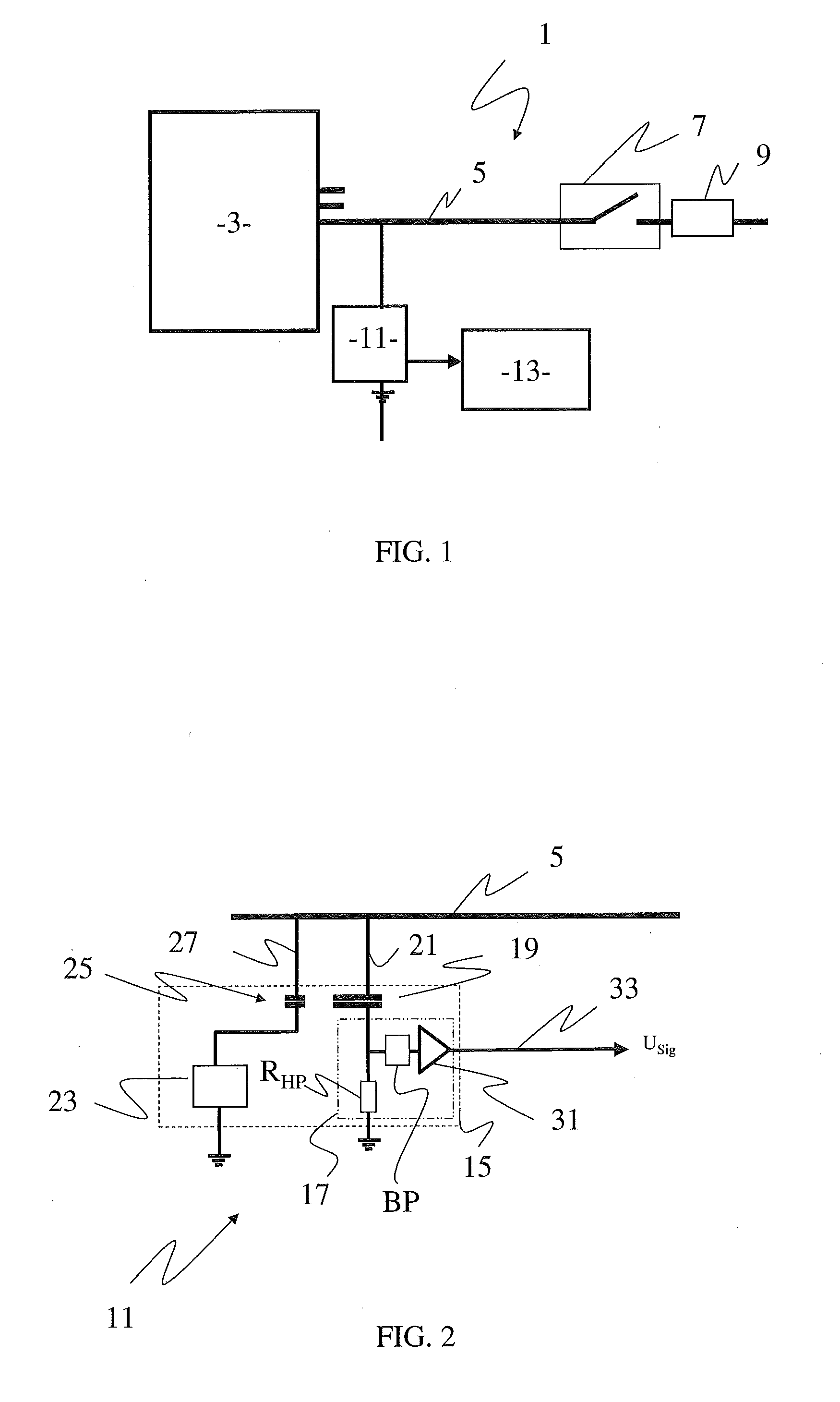
[0046]FIG. 3 shows a partial discharge sensor 11 which differs from the embodiment of FIG. 2 only by the fact that the second high voltage conductor 27 is connected within the housing 15 to the first high voltage conductor 21. Therefore, there is only one high voltage conductor 21 to be connected to the high voltage line, the bus duct 5, meaning that the installation of the partial discharge sensor 11 is the same as those already used.

[0047]As could be seen on FIGS. 2 and 3, the coupling capacitor 19 and the calibration capacitor 25 are two distinct capacitors.

first embodiment

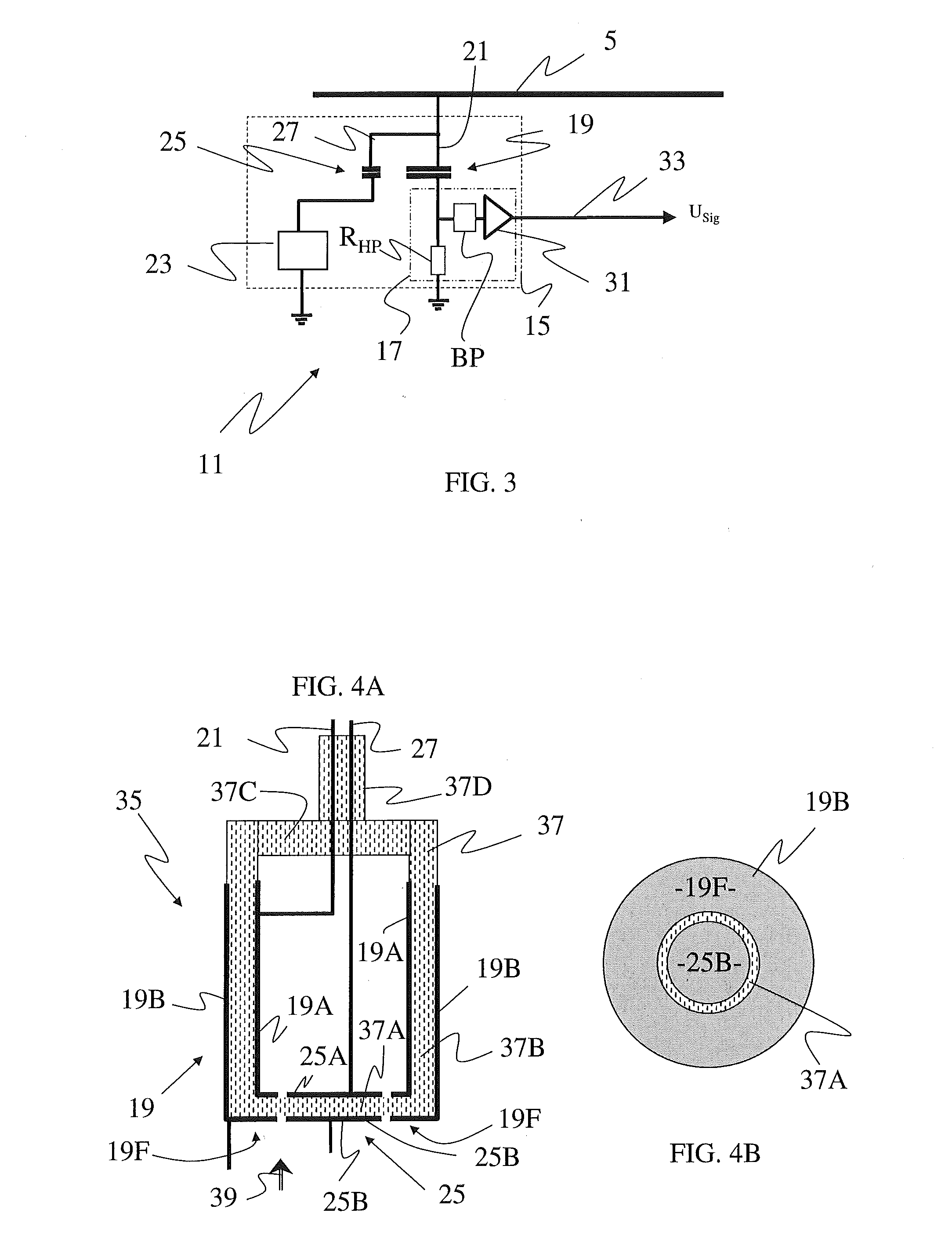
[0048]In order to gain in construction space, it is foreseen to realize both capacitors 19 and 25 as one constructive unit, as a dual capacitor unit 35 as shown for example in FIGS. 4A and 4B which are a schematic representation of a dual capacitor of the partial discharge sensor according to a

[0049]The dual capacitor 35 comprises a hollow cylindrical shaped isolator 37, in particular with a bottom 37A, cylindrical side walls 37B, a top wall 37C that has a connection chimney 37D. The isolator may have a wall thickness of 5 mm, a height of 5 cm and an outer diameter of 5 cm and can be made of a plastic composite.

[0050]Also shown are the high voltage conductors 21 and 27 which are traversing the chimney 37D and that are connected respectively to the high voltage part electrodes 19A of coupling capacitor 19 and 25A of calibration capacitor 25.

[0051]These electrodes 19A and 25A are located on the inner side of the hollow insulator 37. On the opposite side of the walls 37A and 37B, on th...

third embodiment

[0058]In FIG. 5 is shown a schematic representation of the partial discharge sensor 11 according to a

[0059]This embodiment differs from that shown in FIG. 3 by the fact that on the high voltage side, the coupling capacitor 19 and the calibration capacitor 25 have a common electrode 41.

[0060]This embodiment can be realized in slightly modifying the dual capacitor 35 shown in FIG. 4A.

[0061]Such a modified dual capacitor 35 is shown in FIGS. 6A and 6B which are a schematic representation of the dual capacitor of the partial discharge sensor according a second embodiment.

[0062]The dual capacitor 35 in FIG. 6A only differs from that shown in FIG. 4A by the fact that there is only one common high voltage conductor 43, replacing conductors 21 and 27, and that the high voltage electrodes 19A and 25A on the inner side of the isolator 37 are joined to form a common high voltage electrode 41.

[0063]Even with a common electrode 41, the surfaces of the electrodes 19B and 25B are chosen in such a ...


PUM


Abstract

The present invention relates to a partial discharge sensor for a high-voltage insulation monitoring device comprising a housing and located in the housing a measurement circuit for measurement of partial discharges in a high voltage system to be tested and a coupling capacitor having one electrode connected to the measurement circuit and the other electrode to a first high voltage conductor to be connected to a high voltage line of the system to be tested, wherein it further comprises a calibration circuit located in the housing and comprising a calibration capacitor having one electrode connected to the calibration circuit and the other electrode connected to said first or a second high voltage conductor to be connected to a high voltage line.

Description

[0001]The present invention relates to a partial discharge sensor for a high-voltage insulation monitoring device, in particular but not only for measuring partial discharges in the stator windings of large electrical generators of a power plant.BACKGROUND OF THE INVENTION[0002]Partial discharges (PD) are locally occurring electric discharges that partially bridge the insulation between conductors, in particular used in high voltage electrical generation.[0003]They are the result of insulation defects when the electrical field is locally beyond the breakdown strength. Such partial discharges may even lead to further degradation of the insulation between the conductor and even breakdown.[0004]Therefore, the monitoring of partial discharges in high voltage systems is needed to prevent dysfunctioning and damages in a power generation chain. In addition, it is a helpful tool in order to plan shut downs and maintenance of the equipment or replacements.[0005]In industry, measurement of pa...

Claims


Application Information

Patent Timeline
IPC IPC(8): G01R31/14
CPCG01R15/16G01R31/14G01R35/005G01R31/1227
Inventor HOBELSBERGER, MAXIMILIAN
Owner GENERAL ELECTRIC TECH GMBH
Why Eureka
Try Eureka