Method and radar system for repetition jammer and clutter supression

Active Publication Date: 2013-09-12
SAAB AB
View PDF8 Cites 4 Cited by
  • Summary
  • Abstract
  • Description
  • Claims
  • Application Information

AI Technical Summary

Benefits of technology

[0008]With the above description in mind, then, an aspect of the present invention is to provide an improved solution of repetition jammer suppression and/or clutter s

Problems solved by technology

A weakness of using these present solutions, however, is that they require advanced control of the transmit and/or receive antenna pattern.
These present solutions

Method used


Image

  • Method and radar system for repetition jammer and clutter supression
  • Method and radar system for repetition jammer and clutter supression
  • Method and radar system for repetition jammer and clutter supression

Examples


Example

[0045]Examples of the present invention relate, in general, to the field radar systems, in particularly, to methods and systems for deceptive transmission and suppression of jammers and / or clutter when detecting the presence and determining the direction of targets.

[0046]Examples of the present invention will be described more fully hereinafter with reference to the accompanying drawings, in which examples of the invention are shown. This invention may, however, be embodied in many different forms and should not be construed as limited to the examples set forth herein. Rather, these examples are provided so that this disclosure will be thorough and complete, and will fully convey the scope of the invention to those skilled in the art. Like reference signs refer to like elements throughout.

[0047]All the FIGS. 1 to 13 are schematically illustrated.

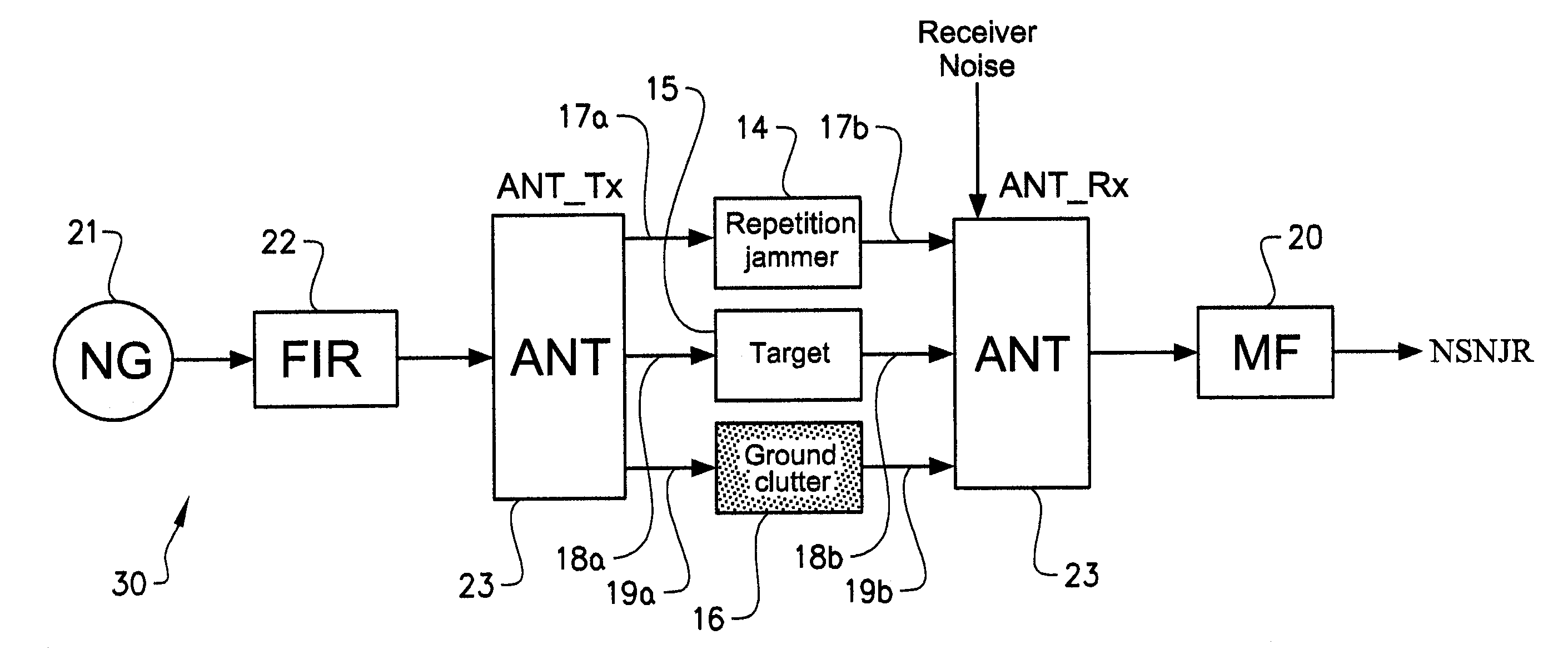
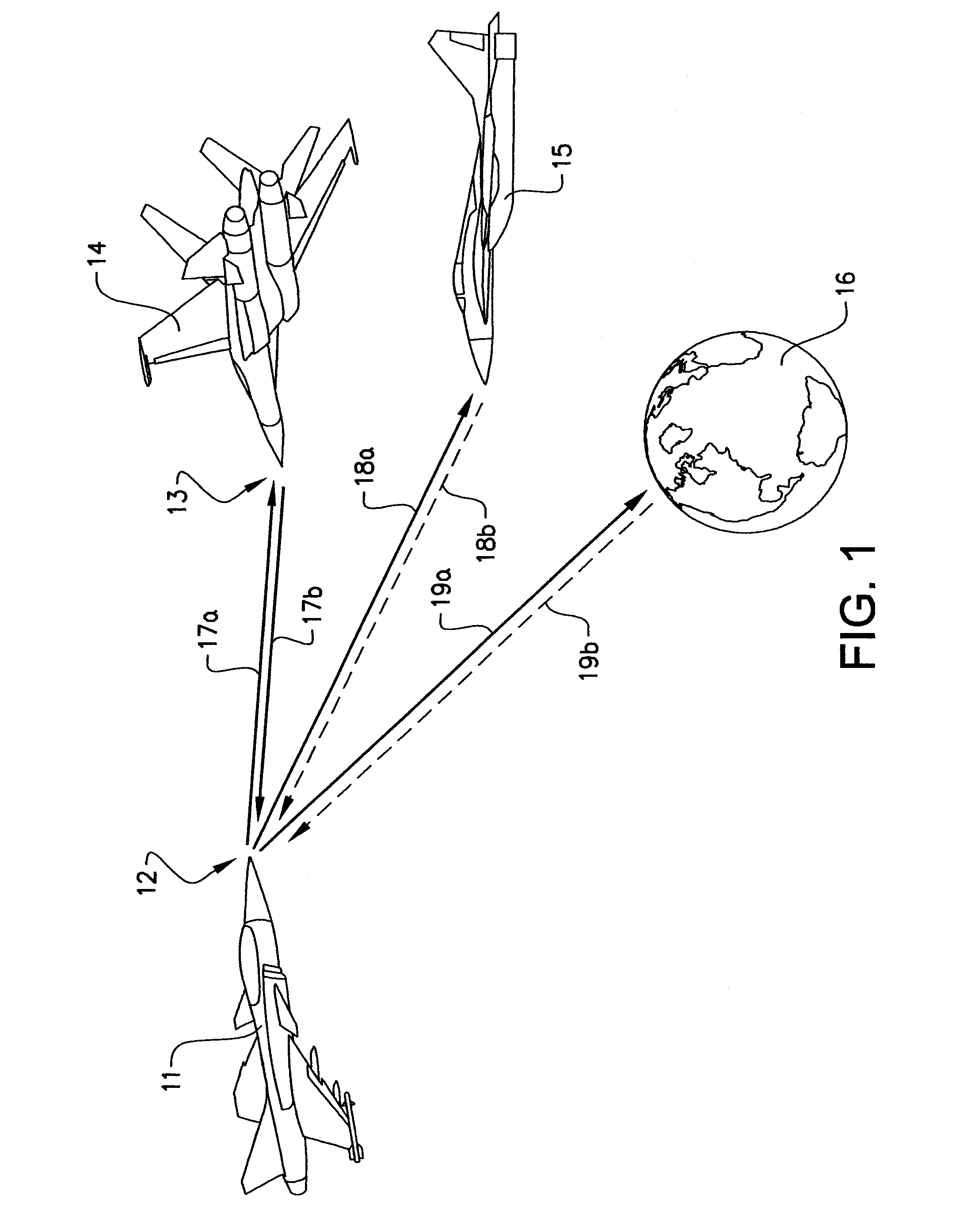
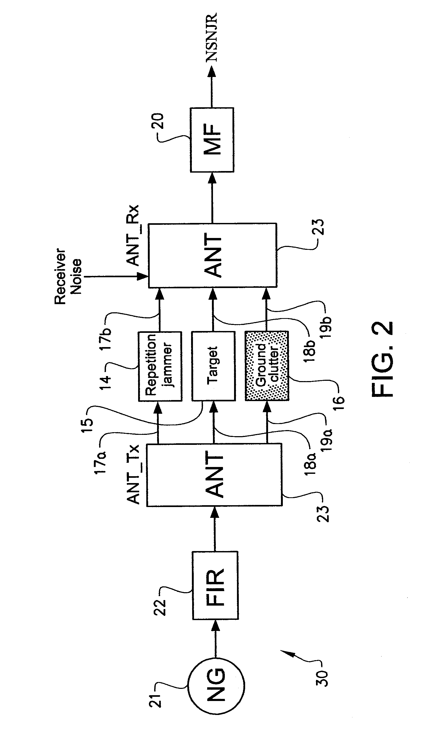
[0048]A scenario for suppression of jammers and / or clutter according to the present invention is schematically shown in FIG. 1. The radar s...


PUM


Abstract

A method for suppressing repetition jammer signals and/or clutter signals by using a radar system wherein said radar system comprises, at least one wideband arbitrary waveform generator, for creating arbitrary waveforms, and at least one antenna operating with wide instantaneous bandwidth, enabling direction dependent waveform radiation, wherein said method comprises the steps of transmitting different waveforms in different directions; adapting transmitted waveforms in different directions depending on received waveforms such that a normalised signal to noise-jammer ratio, NSNJR, is maximized; and thereby providing received signals from repetition jammers and/or clutter that are substantially orthogonal to a received signal from a target; thereby achieving suppression of the repetition jammers and/or clutter.

Description

TECHNICAL FIELD[0001]The present invention relates to the field of radar systems, and more particularly, to systems and techniques for minimizing system performance degradation caused by jamming or clutter.[0002]The present invention relates to a method and a radar system used to suppress repetition jammer signals and / or clutter signals.BACKGROUND ART[0003]There exist various examples of methods and systems for repetition jammer suppression and clutter suppression. Today, the known solutions for repetition jammer suppression and clutter suppression are usually based on adaption of the transmitter and / or receiver to form nulls in the antenna pattern in one or more directions corresponding to jammers and / or clutter. A weakness of using these present solutions, however, is that they require advanced control of the transmit and / or receive antenna pattern.[0004]Further, a common way to minimize system performance degradation caused by jamming is to create deterministic and / or adaptive ca...

Claims


Application Information

Patent Timeline
IPC IPC(8): G01S7/36
CPCG01S7/2813G01S7/36
Inventor FALK, KENT
Owner SAAB AB
Why Eureka
Try Eureka