
Touch-type inputting device and method for controlling the same

Active Publication Date: 2013-09-12
MURATA MFG CO LTD
View PDF20 Cites 12 Cited by
  • Summary
  • Abstract
  • Description
  • Claims
  • Application Information

AI Technical Summary

Benefits of technology

The present invention provides a touch-type inputting device and a method for controlling it that overcomes the problems of existing devices.

Problems solved by technology

However, there has been the problem of poor light transmittance, due to many laminated layers.
Further, there is a need for larger numbers of components and processes, which involves an increased cost.
Further, position information and pressing-force information are detected separately, which has induced the problem of complicacy of signal processing.
This necessitates connecting all of these fine wires to an operational processing portion, thereby inducing the problem of significant complicacy of the structure.Patent Document 1: JP 5-61592 APatent Document 2: JP 2006-163618 A

Method used


Image

  • Touch-type inputting device and method for controlling the same
  • Touch-type inputting device and method for controlling the same
  • Touch-type inputting device and method for controlling the same

Examples


Embodiment Construction

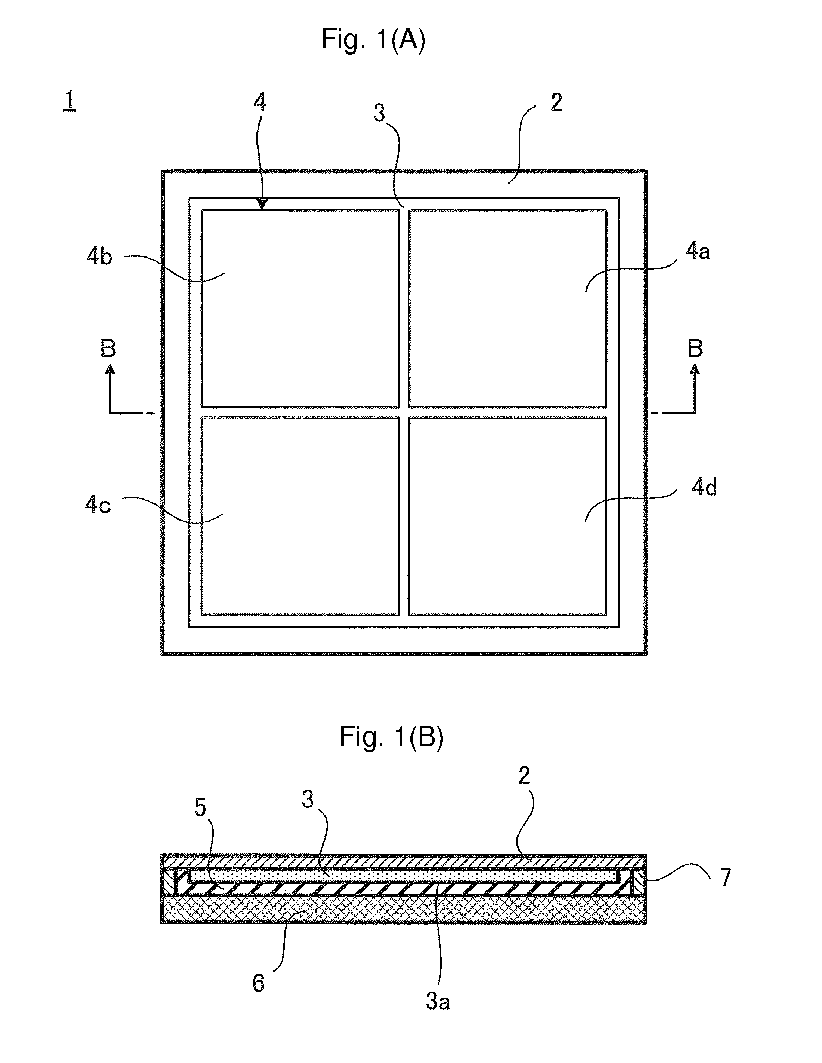
[0058]FIGS. 1(A) and 1(B) illustrate a touch panel 1 included in a touch-type inputting device according to an embodiment of the present invention. In FIGS. 1(A) and 1(B), FIG. 1(A) is a plan view, and FIG. 1(B) is a cross-sectional view taken along line B-B in FIG. 1(A). Further, in the cross-sectional view FIG. 1(B), the respective components are illustrated in such a way as to exaggerate their thicknesses.

[0059]As illustrated in FIG. 1(B), the touch panel 1 has a cross-sectional structure configured by a sheet-type protective member 2, a piezoelectric sheet 3 having a piezoelectric characteristic, a rubber-type elastic member 5, and a base member 6 which are laminated in the mentioned order. More specifically, the piezoelectric sheet 3 is attached to the protective member 2, and the rubber-type elastic member 5 is embedded in the space between the piezoelectric sheet 3 and the base member 6 which are separated from each other by a spacer 7 inserted between the protective member 2...


PUM


Abstract

A piezoelectric sheet included in a touch panel is provided with a split electrode having a plurality of electrode parts. Lattice-shaped coordinates are set in the touch panel, and voltages generated in the respective electrode parts through pressing manipulations with a predetermined load on the respective lattice points are preliminarily stored in a storage portion as reference voltages. During actual use, actually-measured voltages induced in the respective electrode parts due to a pressing manipulation are detected by a detection portion. The ratios of the measured voltages to the reference voltages are calculated by an operation portion, and the average thereof and the standard deviation thereamong are determined. The coordinates of the pressed position are determined from the coordinates of four lattice points in the ascending order of standard deviations. The load is multiplied by the ratio to determine the pressing force of the lattice point having a minimum standard deviation.

Description

CROSS REFERENCE TO RELATED APPLICATIONS[0001]The present application is a continuation of International application No. PCT / JP2011 / 072197, filed Sep. 28, 2011, which claims priority to Japanese Patent Application No. 2010-232157, filed Oct. 15, 2010, the entire contents of each of which are incorporated herein by reference.FIELD OF THE INVENTION[0002]The present invention relates to touch-type inputting devices and methods for controlling the same and, more particularly, relates to touch-type inputting devices employing piezoelectric sheets and methods for controlling the same.BACKGROUND OF THE INVENTION[0003]In recent years, there have been significant increases of inputting devices which employ so-called touch-panel systems, namely, touch-type inputting devices. In cellular phones, portable gaming machines, and portable music players, as well as in bank's ATMs and ticket-vending machines in stations, there have been largely increased apparatuses which employ touch panel systems as...

Claims


Application Information

Patent Timeline
IPC IPC(8): G06F3/041
CPCG06F3/0416G06F3/0414G06F3/0488G06F16/24578G06F2111/08
Inventor ANDO, MASAMICHIKONDO, NOBUHIRO
Owner MURATA MFG CO LTD
Features
  • Generate Ideas
  • Intellectual Property
  • Life Sciences
  • Materials
  • Tech Scout
  • Unparalleled Data Quality
  • Higher Quality Content
  • 60% Fewer Hallucinations
Learn More