Vehicle Peripheral Area Observation System

a technology of observation system and vehicle, which is applied in the field of vehicle peripheral area observation system, can solve the problems of erroneous optical flow detection, erroneous optical flow measurement, and inability to detect the presence of another vehicle accurately and easily

Inactive Publication Date: 2013-09-12
CLARION CO LTD
View PDF7 Cites 46 Cited by
  • Summary
  • Abstract
  • Description
  • Claims
  • Application Information

AI Technical Summary

Benefits of technology

[0010]The present invention has been made in view of the foregoing, and provides a vehicle peripheral area observation system capable of accurately and easily detecting a moving object that has a possibility of hitting against the vehicle by avoiding an erroneous recognition that would otherwise occur due to an apparent motion between images.

Problems solved by technology

However, as an optical flow is influenced by even a local apparent motion between the images, an erroneous optical flow can be measured in a circumstance in which the luminance value other than that of a moving object such as a pedestrian changes from moment to moment.
That is, there has been a problem that even if there is no obstacle in the three-dimensional space, an erroneous optical flow can be measured in a circumstance in which the luminance value changes with time.
Thus, there is a possibility that when an erroneous optical flow is measured as described above, the presence of another vehicle may be erroneously recognized though such a vehicle is not actually present.

Method used


Image

  • Vehicle Peripheral Area Observation System
  • Vehicle Peripheral Area Observation System
  • Vehicle Peripheral Area Observation System

Examples


first embodiment

[0027]Hereinafter, a first embodiment will be described.

[0028]A primary object of a vehicle peripheral area observation system in accordance with this embodiment is to provide a user-friendly vehicle peripheral area observation system that, by detecting a region of an apparent motion due to water vapor or a light source fluctuation, invalidates a result of detection of a moving object in the region and suppresses error warnings that would otherwise be output due to the apparent motion.

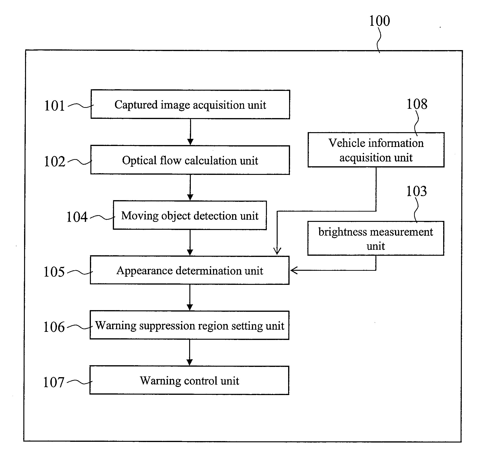
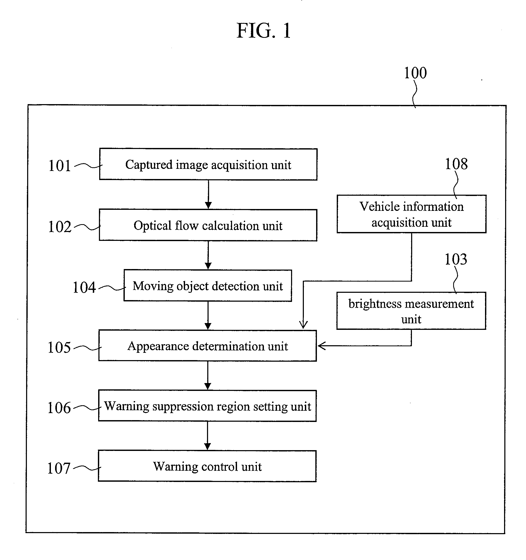
[0029]The vehicle peripheral area observation system, in order to detect a moving object around a vehicle, calculates optical flows between images captured with an on-vehicle camera at preset time intervals, and if a given number or more of pixels having flows in an identical direction aggregate, outputs information on the pixels as a moving object.

[0030]Water vapor that can be a cause of an error warning has the following characteristics (1) to (5): (1) the contrast is low in the daytime; (2) when the...

embodiment 1

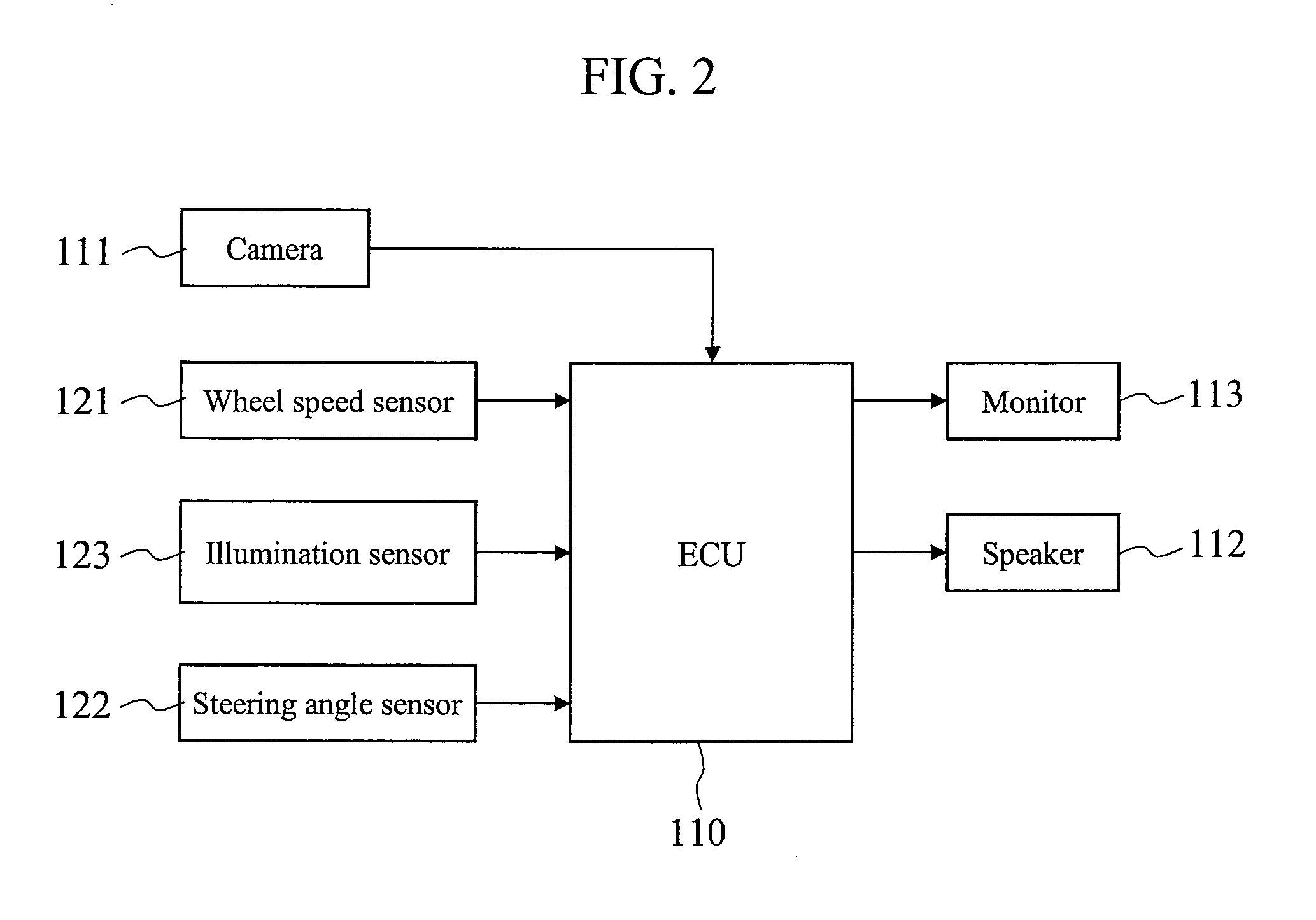
[0039]Next, an embodiment of a vehicle peripheral area observation system 100 will be described with reference to the drawings. This embodiment concerns the vehicle peripheral area observation system 100 in which an image of the peripheral area of a vehicle is captured with an on-vehicle camera 111, and, when a moving object that has a possibility of hitting against the vehicle 120 is detected, a warning is output.

[0040]First, terms used in the following description will be defined. A motion vector representing the amount of movement between image coordinates calculated from two images, which have been captured with an imaging device at different time points, will be referred to as an optical flow.

[0041]There are cases where, even when an object has not actually moved, optical flows are calculated as the shape of the object changes from moment to moment like water vapor. There are also cases where, when a light source illumination environment of a vehicle, another vehicle, or an obj...

second embodiment

[0115]Next, a second embodiment will be described with reference to FIG. 11.

[0116]An overall flow of a process in this embodiment is substantially the same as that in the first embodiment. Thus, only portions that differ from those in the first embodiment will be described. FIG. 11 is a diagram illustrating a hardware configuration of the second embodiment.

[0117]In the second embodiment, a configuration is provided in which a video correction unit 165 receives a video from the camera 161. The video correction unit 165 performs overhead view conversion on each of videos from cameras mounted on the front, rear, right, and left of the vehicle to merge the videos, thereby generating an overhead view monitor image. The video correction unit 165 then transmits a video including the thus generated overhead view monitor image to the CPU 160. The CPU 160 detects an apparent motion or detects a moving object.

[0118]Detection of an apparent motion from the overhead view monitor image is substan...


PUM


Abstract

To provide a vehicle peripheral area observation system that can, with a simple configuration, detect a pedestrian who has a possibility of hitting against the vehicle by removing an appearance motion due to water vapor or a light source fluctuation. A water vapor region is detected from motion information and luminance information from videos captured with an on-vehicle camera, and recognition of a moving object in the water vapor region is invalidated for a given period of time.

Description

BACKGROUND[0001]1. Technical Field[0002]The present invention relates to a vehicle peripheral area observation system that detects, from images of the peripheral area of a vehicle captured with an on-vehicle camera, a pedestrian who has a possibility of approaching the vehicle.[0003]2. Background Art[0004]So far, a system has been conceived that has one or more cameras mounted on a moving object such as a vehicle and that prevents an accident by recognizing an obstacle present in an environment around the vehicle and notifying a driver of the presence of the obstacle as needed. For example, a technology of calculating optical flows from a plurality of images captured at different timings and merging motions between the images at corresponding points to calculate a motion between the images has been developed. An image processing device that recognizes a moving object such as a pedestrian or a bicycle by calculating such a motion between the images is known.[0005]For example, Patent ...

Claims


Application Information

Patent Timeline
Patent Type & Authority Applications(United States)
IPC IPC(8): G08G1/16
CPCG06K9/00805G08G1/166G06K9/00825G06T2207/30261G06T7/20G06V20/584G06V20/58
Inventor KIYOHARA, MASAHIROUCHIDA, YOSHITAKAMURAMATSU, SHOJIIRIE, KOTA
Owner CLARION CO LTD
Why Eureka
Try Eureka