Virtual image display device

a virtual image and display device technology, applied in the field of virtual image display devices, can solve the problems of increasing the weight of the device for image formation, the limited design of the external appearance of the device, and the increase in the load on the wearer, so as to reduce the feeling of weight, suppress the optical fiber, and facilitate viewing

Active Publication Date: 2013-09-12
SEIKO EPSON CORP
View PDF1 Cites 80 Cited by
  • Summary
  • Abstract
  • Description
  • Claims
  • Application Information

AI Technical Summary

Benefits of technology

[0006]An advantage of some aspects of the invention is to provide a virtual image display device that, when image light and external light are observed in parallel, enables visibility adjustment for observation of the external light and can suppress an increase in the size of the device.
[0011]In still another aspect of the invention, the scanning optical system is arranged to be located closer to the nose side than the eye of the wearer during wearing of the virtual image display device and arranged to be located closer to the wearer than the virtual-image forming member. Therefore, it is possible to suppress the worn device from excessively projecting to the side and the front side, suppress an increase in the feeling of weight due to deviation of the center of gravity of the device, and increase a degree of freedom of design of the device.
[0012]In yet another aspect of the invention, the virtual-image forming member is formed integrally to be located on the inner surface that is on the wearer side during wearing of the virtual image display device among the surfaces of the visibility adjusting member. Therefore, it is possible to realize a reduction in the weight and a reduction in the size of the device. Further, since a gap is not formed between the virtual-image forming member and the visibility adjusting member, it is possible to more satisfactorily recognize the virtual image and the external image.
[0013]In still yet another aspect of the invention, the virtual-image forming member is a film to be irradiated supported by the visibility adjusting member. Therefore, it is possible to stably support the thin film-like virtual-image forming member with the visibility adjusting member.
[0018]In a still further aspect of the invention, the signal-light modulating unit includes a combined-light forming unit configured to form, as the signal light, combined light obtained by combining R light, G light, and B light and an optical fiber configured to propagate the signal light formed by the combined-light forming unit to the scanning optical system. In the signal-light modulating unit, the combined-light forming unit is arranged in a position corresponding to the ear side. The optical fiber extends along a path from the periphery of the ear to the periphery of the nose through the periphery of the eye along a face shape of the wearer during wearing of the virtual image display device to propagate the modulated signal light from the combined-light forming unit to the scanning optical system. Therefore, it is possible to disperse the weight of the entire device. It is possible to reduce the feeling of weight during the wearing of the virtual image display device by dispersing the load due to the device applied to the wearer and adjusting the center of gravity of the device and enable the wearer to more comfortably perform viewing. Further, it is possible to suppress the optical fiber from projecting to the side and the front side and increase a degree of freedom of design of the entire device.

Problems solved by technology

According to the increase in size, it is likely that the weight of the device for image formation increases, a load on the wearer increases when the wearer wears the device, and design of the external appearance of the device is limited.

Method used


Image

  • Virtual image display device
  • Virtual image display device
  • Virtual image display device

Examples


first embodiment

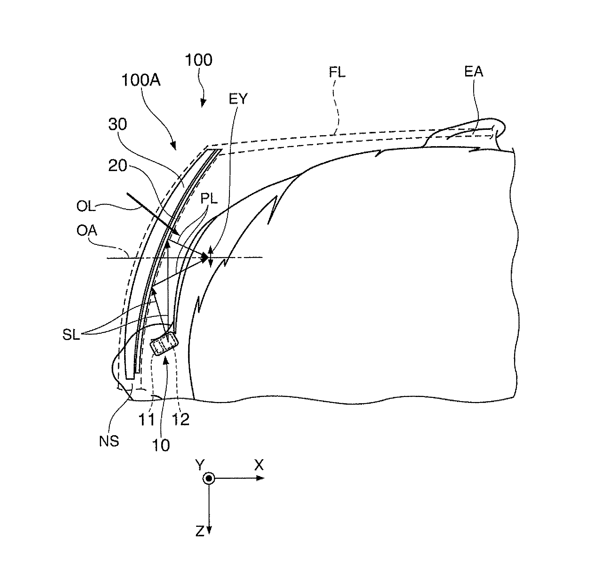
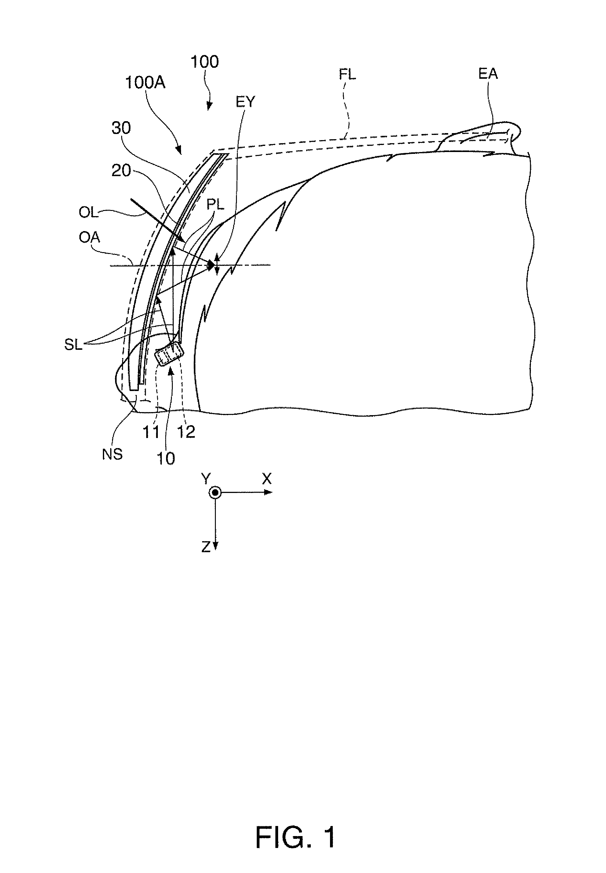
[0032]A virtual image display device according to a first embodiment of the invention is explained in detail below with reference to the drawings.

[0033]A virtual image display device 100 according to this embodiment shown in FIG. 1 is a head mounted display having an external appearance like glasses. The virtual image display device 100 can allow a wearer, who should be an observer, wearing the virtual image display device 100 to recognize image light formed by a virtual image and allow the wearer to observe an external image in a see-through manner. In FIG. 1, a state in which the wearer wears the virtual image display device 100 is shown while being partially enlarged. A part of the virtual image display device 100 is omitted. Specifically, a first display device 100A is a section that forms a virtual image for the right eye in the virtual image display device 100. The virtual image display device 100 includes the first display device 100A for the right eye and a second display de...

second embodiment

[0060]A virtual image display device according to a second embodiment is explained below. The virtual image display device according to this embodiment is a modification of the virtual image display device 100 according to the first embodiment. Unless specifically explained, it is assumed that the virtual image display device is the same as the virtual image display device 100 according to the first embodiment.

[0061]As shown in FIG. 5, in a first display device 200A included in a virtual image display device 200 according to this embodiment, a virtual-image forming member 220 and a visibility adjusting member 230 are integrated. More specifically, the semitransparent reflection film 20a is formed on an inner surface 230a, which is a surface opposed to a wearer side, among the surfaces of the visibility adjusting member 230. The semitransparent reflection film 20a functions as the virtual-image forming member 220. In other words, the semitransparent reflection film 20a functioning as...

third embodiment

[0063]A virtual image display device according to a third embodiment is explained below. The virtual image display device according to this embodiment is a modification of the virtual image display device 100 according to the first embodiment. Unless specifically explained, the virtual image display device is the same as the virtual image display device 100 according to the first embodiment.

[0064]As shown in FIG. 6, a virtual-image forming member 320 of a first display device 300A included in a virtual image display device 300 according to this embodiment includes a transparent substrate TP and a hologram element HE. Specifically, the virtual-image forming member 320 has a configuration in which the hologram element HE, which is an example of a diffraction grating, is provided on the transparent substrate TP that allows light to pass. The hologram element HE is formed on a region to be irradiated, which is a range in which the scanning lights SL are irradiated. The hologram element ...


PUM


Abstract

Image lights formed by a light emitting device and a virtual-image forming member and external light transmitted through a visibility adjusting member and the virtual-image forming member can be observed in parallel in a see-through manner. In the observation of the external light, the visibility adjusting member enables visibility adjustment corresponding to the eyesight of a wearer. Therefore, the wearer can observe the external light without wearing a device for visibility adjustment such as glasses. Therefore, it is possible to suppress an increase in the size of a virtual image display device.

Description

BACKGROUND[0001]1. Technical Field[0002]The present invention relates to a virtual image display device such as a head mounted display that is used while being mounted on the head.[0003]2. Related Art[0004]In recent years, as a virtual image display device for enabling formation and observation of a virtual image such as a head mounted display, various head mounted displays that scan an image light and project an image on the retinas of the eyes are proposed (see JP-A-2007-178941 (Patent Literature 1), WO2009 / 041055 (Patent Literature 2), and JP-T-2007-537465 (Patent Literature 3)). In particular, a head mounted display configured “see-through” in order to superimpose image light for forming a virtual image and external light, which is light from the external environment, one on top of the other is proposed (see, for example, Patent Literature 1).[0005]However, when a wearer, who is an observer, is, for example, near-sighted and needs to correct the eyesight using a device for visib...

Claims


Application Information

Patent Timeline
Patent Type & Authority Applications(United States)
IPC IPC(8): G02B27/01
CPCG02B27/0176G02B2027/0178G02B27/0172G02B2027/0156
Inventor TAKEDA, TAKASHITOTANI, TAKAHIROKOMATSU, AKIRATAKAGI, MASAYUKIMIYAO, TOSHIAKI
Owner SEIKO EPSON CORP
Why Eureka
Try Eureka