
Electrical plug connector with tolerance compensation

a technology of tolerance compensation and plug parts, which is applied in the direction of coupling device connection, contact member manufacturing, electrical apparatus, etc., can solve the problems of exposing the soldered connection of the plug parts to mechanical stress, especially great problems, and difficulties, etc., and achieves the effect of reducing the cost of production, facilitating plastic deformation, and special design tolerance compensation

Active Publication Date: 2013-09-12
CONINVERS
View PDF9 Cites 2 Cited by
  • Summary
  • Abstract
  • Description
  • Claims
  • Application Information

AI Technical Summary

Benefits of technology

This patent is about a new design for an electrical plug connector that allows for easier and more accurate alignment of plug parts when soldered to a circuit board. The connector has a tolerance compensation part that is S-shaped, U-shaped, circular, spiral-shaped, or wavelike in contour. The tolerance compensation part can displace the plug connection element in any direction parallel to the circuit board. The design also ensures that the tolerance compensation part does not interfere with the alignment process and prevents unnecessary force and deformation on the plug connection elements and soldering pins. The plug connector is made of a flexible material that allows for easy plastic deformation to permanently align the insulating body with the plug parts. The tolerance compensation part is a cost-effective solution and can be produced as a stamped bent part. The design is especially effective in preventing permanent force and deformation on the soldered joint.

Problems solved by technology

A problem with electrical plug connectors consists of producing socket and pin plug connectors—that can be plugged into each other and of which at least one plug connector is intended for soldering to a circuit board—which, despite a certain misalignment of some or all socket or pin-type plug parts, can be arranged without problems in a tolerance-afflicted receptacle after soldering to the circuit board.
This problem will occur especially when the plug connector to be soldered comprises a large number of plug parts, or when several socket and / or pin-type plug connectors are arranged side-by-side on a circuit board and the electrical connection is to be established via a common group plug in a tolerance-afflicted receptacle.
This problem is especially great with electrical plug connectors that are configured as a surface-mountable component.
If the insulating body of such plug connectors is not positioned exactly as specified in the design, difficulties may also arise when a housing part with the chambers or passages that accept the soldered plug connectors, embracing and / or overlapping the associated insulating body, is to be installed.
However, that does not correct the misalignment of the plug parts so that the matching plug parts of the matching plug connector are difficult to join with the plug parts of the soldered plug connector, subjecting the soldered connection of the plug parts to mechanical stress.
Over the long term, this may damage the soldered connections.
In addition, the plug parts of the at least one soldered plug connector and / or the matching plug parts of the matching plug connector may be damaged or possibly even become unusable.

Method used


Image

  • Electrical plug connector with tolerance compensation
  • Electrical plug connector with tolerance compensation
  • Electrical plug connector with tolerance compensation

Examples


Embodiment Construction

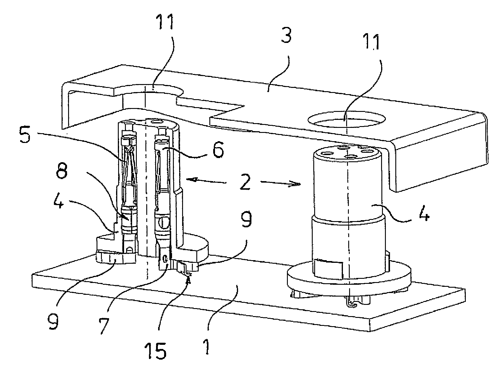
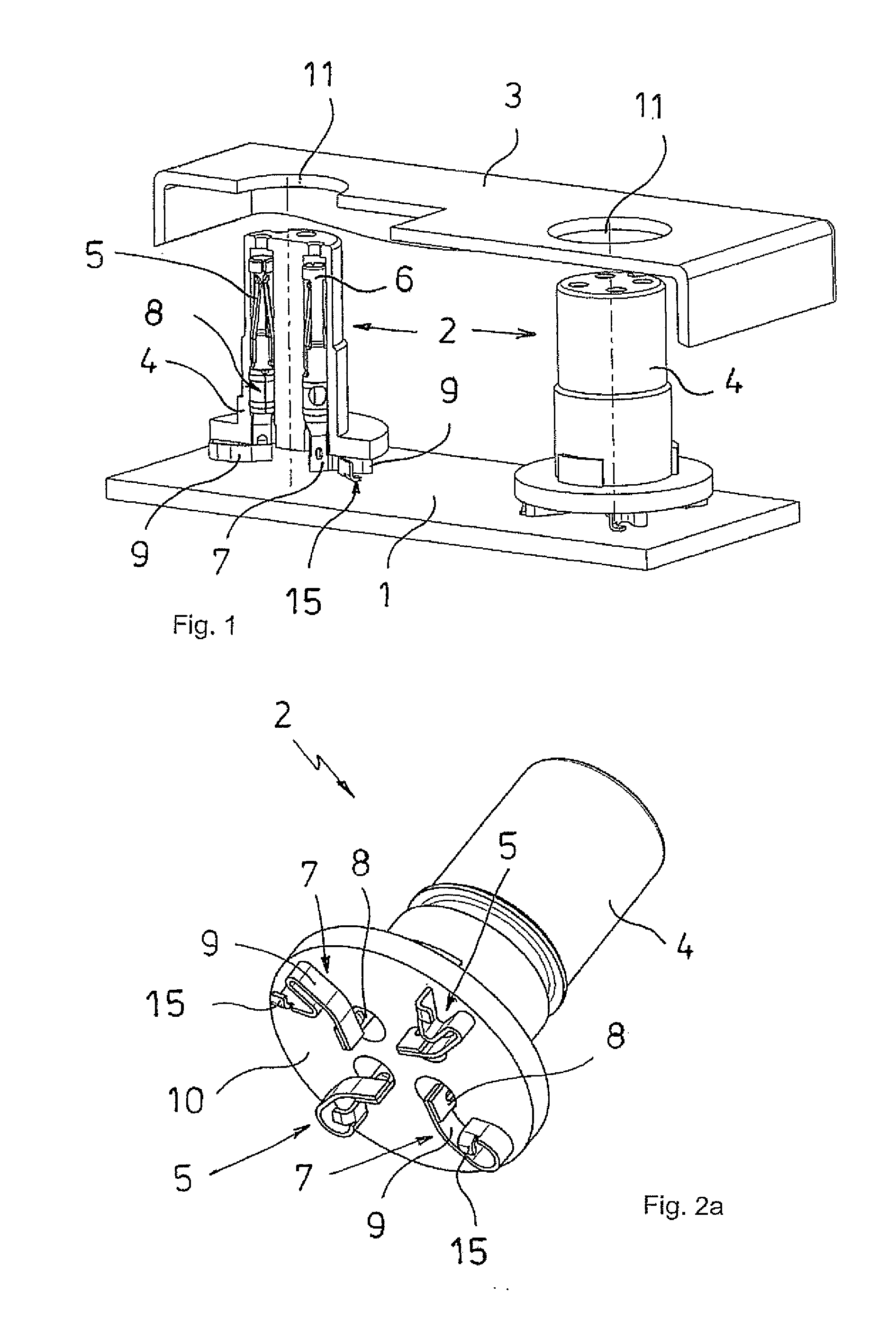
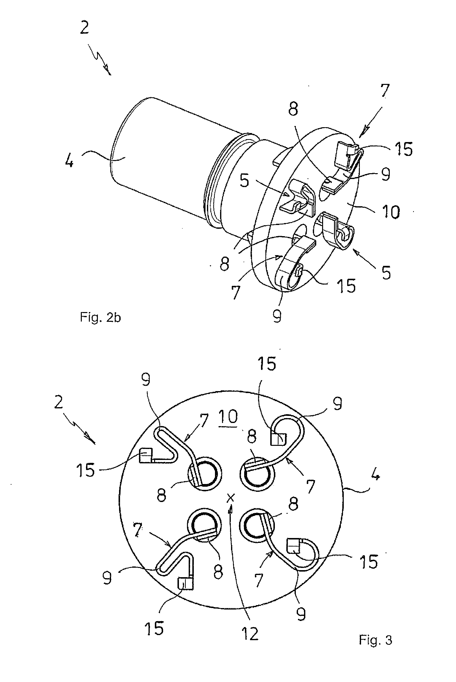
[0027]By way of example, FIG. 1 shows a plug connector assembly with only two electrical plug connectors 2 that are arranged side-by-side at a distance from each other on a circuit board 1 (not shown) to which they are soldered. The plug connectors 2 are provided as surface-mountable components. Above the circuit board 1 with the plug connectors 2, the Figure shows a receptacle 3 through which the plug connectors 2 are intended to pass. The receptacle may consist of a flange, for example, with which the plug connectors 2 with the circuit board 1 are attached to a housing, or may consist directly of a housing wall of a housing holding the plug connectors 2, the circuit board 1, and possibly additional elements. The plug connectors 2 comprise a cylindrical insulating body 4 with four plug parts 5 held therein. The plug parts 5 are visible in the left plug connector 2 that is shown in a longitudinal section view.

[0028]The plug parts 5 comprise plug connection elements 6 and solder conn...


PUM


Abstract

An electrical plug connector with an insulating body that holds at least one metallic plug part that comprises at least one solder connection element that can be soldered to a circuit board, and at least one plug connection element for a matching plug part, both of which are connected with each other via a central piece of the plug connection element. The solder connection element may be connected via a tolerance compensation part with the central piece of the plug part, or directly with the plug connection element, in such a way that, relative to the position of the solder connection element—with the solder connection element soldered to the circuit board—the position of the plug connection element can be changed in any direction, parallel to the plane of the circuit board. In addition, the invention relates to a plug connector assembly.

Description

CROSS-REFERENCE TO RELATED APPLICATION[0001]The present application claims priority under 35 USC §119 to European Patent Application No. 12 401 041.4 filed Mar. 12, 2012, the entire disclosure of which is incorporated herein by reference.TECHNICAL FIELD OF THE INVENTION[0002]The invention relates to an electrical plug connector with an insulating body that holds at least one metallic plug part that comprises at least one solder connection element that can be soldered to a circuit board, and at least one plug connection element for a matching plug part, with at least the solder connection element projecting at least partially beyond the insulating body, as well as a plug connector assembly.DESCRIPTION OF THE RELATED ART[0003]A problem with electrical plug connectors consists of producing socket and pin plug connectors—that can be plugged into each other and of which at least one plug connector is intended for soldering to a circuit board—which, despite a certain misalignment of some ...

Claims


Application Information

Patent Timeline
Patent Type & Authority Applications(United States)
IPC IPC(8): H01R13/64
CPCH01R12/57H01R13/111H01R13/64H01R43/16H01R13/6315
Inventor WEHRLE, GERHARDRITTER, HOLGER
Owner CONINVERS
Learn More