Portable machining apparatus tool module

a technology of tool module and machining apparatus, which is applied in the direction of turning machines, manufacturing tools, portable lathes, etc., can solve the problem that the clamping module that supports cutting tools is not typically easy to adjust otherwis

Inactive Publication Date: 2013-09-19
ACTUANT CORP
View PDF6 Cites 18 Cited by
  • Summary
  • Abstract
  • Description
  • Claims
  • Application Information

AI Technical Summary

Benefits of technology

[0010]In yet another aspect, the present invention provides a tool module for a machining apparatus. The machining apparatus includes a clamshell having a stationary portion rotatably supporting a rotatable portion. The tool module comprises a module base supported by the rotatable portion of the clamshell and defining a linear movement slot. A tool slide is configured to support a cutting tool and is movable within the linear movement slot. The tool slide also defines a feed nut recess having an open face. A feed nut is supported in the feed nut recess, and a feed screw is rotatably supported by the feed nut and is rotatable to translate the feed nut and the tool slide within the linear movement slot. The tool module further includes a feed nut bracket disposed proximate the feed nut and within the linear movement slot. The feed nut bracket extends across the open face of the feed nut recess to reinforce the tool slide.

Problems solved by technology

Despite the cutting tool's ability to translate radially relative to the pipe, clamshell modules that support cutting tools are not typically easy to otherwise adjust once connected to the piping structure.
This can be especially problematic when operating on pipes in nuclear reactors because maintenance personnel may only work in radioactively “hot” areas for extremely short time periods.
Moreover, previous cutting tool support modules are typically constructed so that replacement or repair of relatively small parts requires replacement or overhaul of a significant portion of the device.

Method used


Image

  • Portable machining apparatus tool module
  • Portable machining apparatus tool module
  • Portable machining apparatus tool module

Examples


Embodiment Construction

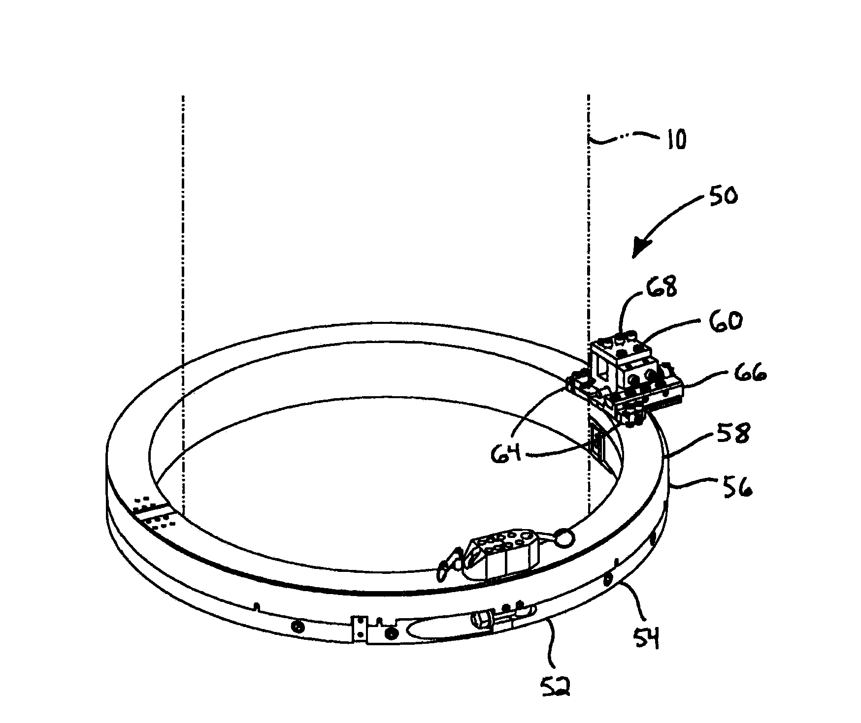
[0021]Referring first to FIG. 1, a machining apparatus 50 connects to a generally cylindrical workpiece 10 (e.g., a pipe) having a weld crown or other work surface. The machining apparatus 50 includes a portable pipe lathe or clamshell 52 as is described in, e.g., U.S. Pat. Nos. 4,739,685, 4,939,964, 5,549,024 and / or 6,619,164, the disclosures of which are hereby incorporated by reference. The clamshell 52 may alternatively take the form of other embodiments that are not described in the above references. In the case of the former, the clamshell 52 generally includes a stationary portion 54 fixedly connected to the pipe 10 and a ring gear housing 56, each of which include adjoining semicircular segments that allow them to be positioned circumferentially around the pipe 10. The stationary portion 54 and the ring gear housing 56 are joined together by bearings internal to the construction (not shown). As such, a rotatable portion 58 supported by the ring gear housing 56 can be made to...


PUM

PropertyMeasurementUnit
shapesaaaaaaaaaa
sizeaaaaaaaaaa
perimeteraaaaaaaaaa

Abstract

A tool module for a machining apparatus including a rotatable portion. The tool module includes at least one adjustment clamp supported by the rotatable portion. A module base is supported by the at least one adjustment clamp and defines a linear movement track. A tool slide is configured to support a cutting tool and is movable along the linear movement track. The at least one adjustment clamp is movable from a release position to a locking position and vice versa, and in both the release position and the locking position the at least one adjustment clamp is connected to the rotatable portion. In the release position the at least one adjustment clamp permits the module base to translate relative thereto, and in the locking position the at least one adjustment clamp engages the module base to inhibit the module base from moving relative thereto.

Description

CROSS-REFERENCE TO RELATED APPLICATION[0001]This application claims the benefit of U.S. Provisional Patent Application No. 61 / 416,956 filed Nov. 24, 2010, the disclosure of which is hereby incorporated by reference in its entirety.STATEMENT CONCERNING FEDERALLY SPONSORED RESEARCH OR DEVELOPMENT[0002]Not applicable.FIELD OF THE INVENTION[0003]This invention relates to portable machining lathes, and particularly cutting tool support modules of clamshell lathes.BACKGROUND OF THE INVENTION[0004]Some components, such as piping that may be part of a pipeline, building, plant machinery, ship, or other structures and devices, are assembled, repaired, or reconditioned in place due to their size, location, accessibility, or the like. Such processes typically include cutting off pipes, preparing pipe joints for welding, and forming welds at piping junctures. One method of cutting off pipes is to use a cutting tool mounted to a “clamshell”. Clamshells are portable pipe lathes that are connected...

Claims


Application Information

Patent Timeline
Patent Type & Authority Applications(United States)
IPC IPC(8): B23B3/22
CPCB23B3/26Y10T82/22B23B3/22B23B5/08
Inventor PLACE, BRENT K.
Owner ACTUANT CORP
Why Eureka
Try Eureka