
Kitchen Appliance for Preparing a Beverage and Method of Operating Same

Active Publication Date: 2013-09-19
HAMILTON BEACH BRANDS
View PDF12 Cites 40 Cited by
  • Summary
  • Abstract
  • Description
  • Claims
  • Application Information

AI Technical Summary

Benefits of technology

This patent is about a new kitchen appliance that can make beverages either by using pressure or by putting them on top and waiting for them to drip. The appliance works like a regular drip coffee maker, but can also be used as a pressurized brewing system.

Problems solved by technology

However, conventional devices have numerous disadvantages.
In addition, known pressurized systems can be loud due to the use of mechanical liquid or air pumps.
Mechanical fluid and air pumps are also relatively expensive components that effect manufacturing costs and the complexity and reliability of the appliance.
Finally, liquid and air pumps may push water through an infusible material too quickly.
While a mechanical pump can quickly produce a brewed beverage, the beverage may be relatively weak or less desirable than a “slower” brew system.

Method used


Image

  • Kitchen Appliance for Preparing a Beverage and Method of Operating Same
  • Kitchen Appliance for Preparing a Beverage and Method of Operating Same
  • Kitchen Appliance for Preparing a Beverage and Method of Operating Same

Examples


first embodiment

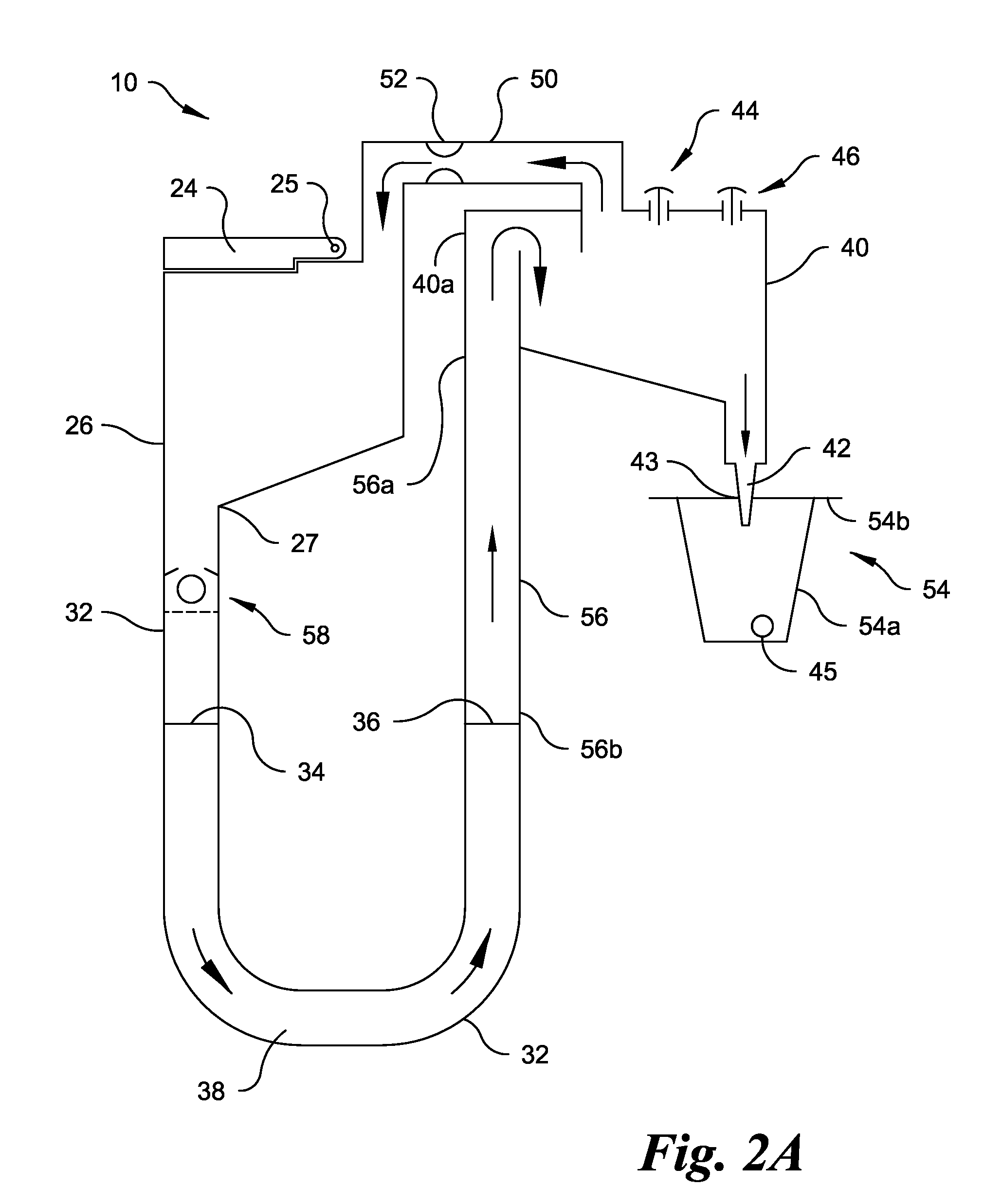
[0064]FIG. 2B illustrates a modified embodiment of the second reservoir 40′ of the present disclosure. The reference numerals of the modified embodiment are distinguishable from those of the previously-described embodiment by a prime symbol (′), but otherwise indicate the same elements as indicated in the first embodiment, except as otherwise specified. While certain like reference numerals may be shown in FIG. 2B, the description of certain similarities between the embodiments may be omitted herein for the sake of brevity and convenience, and, therefore, is not limiting

[0065]The modified embodiment of the second reservoir 40′ includes an additional portion or extension 41′ that preferably extends downwardly below the bottom wall of the second reservoir 40′. The extension 41′ allows the second reservoir 40′ to hold or otherwise store and increased amount of liquid without increasing the height of the housing 12. However, if the discharge port 42′ is not properly positioned (or if th...

fourth embodiment

[0102]The user places the drawer assembly 416 into the housing 412 until an exterior surface of the handle 418 is generally flush with an exterior surface of the housing 412 (see FIG. 10). In the fourth embodiment, the handle 418 is fixedly or non-movably attached to the drawer 468. As described above, the four-bar linkage 490 moves the funnel 472 into the proper position. A vessel is placed or positioned within the recess 414 of the housing 412 to collect or receive the prepared beverage. The user chooses a vessel size, such as through the display 488, and then depresses the on / off button 486 to initiate an operating cycle. Alternatively, the user can simply depress the on / off button 486 to create the same amount of the beverage as the last time an operating cycle was initiated.

[0103]Once an operating cycle is initiated, in one embodiment the PCB references, senses or otherwise communicates with the optional liquid lever sensor to make sure that the fourth reservoir 480 includes a ...


PUM


Abstract

A kitchen appliance includes a first reservoir for receiving a liquid to be used for preparing a beverage and a hot water generator (‘HWG’) which has an inlet end, an outlet end and a passageway therebetween. The inlet end of the HWG is connected to the first reservoir. Liquid from the first reservoir flows into the HWG through the inlet end. A second reservoir is connected to the outlet end of the HWG. The second reservoir includes a discharge port. A fluid path connects the first and second reservoirs and bypasses the HWG. The kitchen appliance is operable for both pressurized brew / heat cycles and un-pressurized brew / heat cycles.

Description

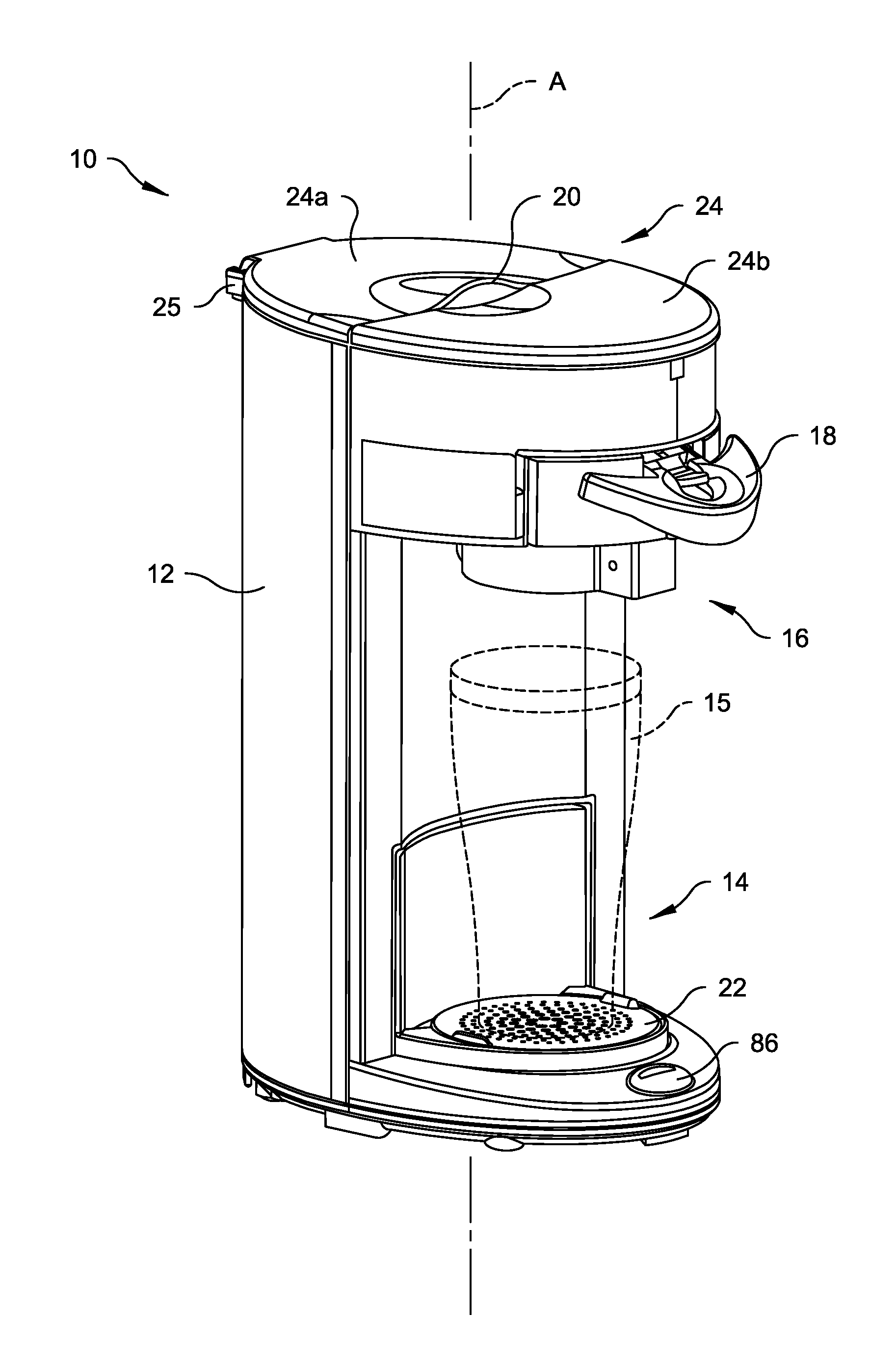
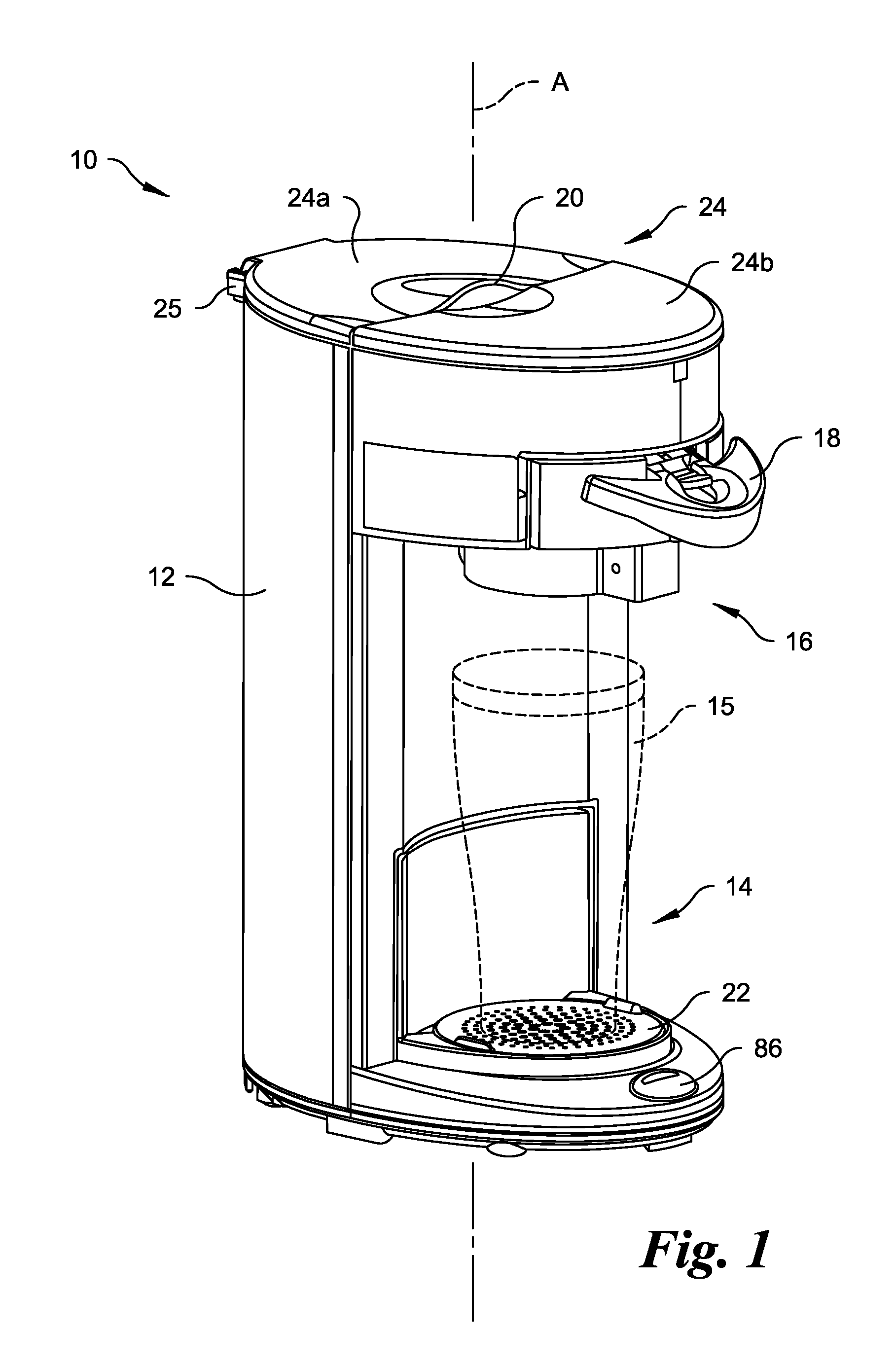
SUMMARY OF THE DISCLOSURE[0001]The present disclosure relates generally to a kitchen appliance for preparing beverage. The subject kitchen appliance can be operated as a pressurized brewing system or as an automatic drip brewing system that operates at ambient pressure.BACKGROUND OF THE DISCLOSURE[0002]Kitchen appliances for preparing a beverage are well known. However, conventional devices have numerous disadvantages. For example, conventional devices generally use a pressurized system (such as espresso, cartridge brewers, etc.) that employ mechanical air or liquid pumps or an unpressurized / ambient system (e.g., percolators, automatic drip coffeemakers, etc.). It is not known to operate a machine in both pressurized (closed) and ambient (open) conditions during different brew or heating cycles. In addition, known pressurized systems can be loud due to the use of mechanical liquid or air pumps. Mechanical fluid and air pumps are also relatively expensive components that effect manuf...

Claims


Application Information

Patent Timeline
IPC IPC(8): A47J31/46
CPCA47J31/462A23F3/18A47J31/46A47J31/407A23F5/262
Inventor STARR, WILLIAM D.HANES, ADAMMULVANEY, PATRICK T.
Owner HAMILTON BEACH BRANDS
Learn More