Vehicle cooling device

Active Publication Date: 2013-09-19
AISIN SEIKI KK
View PDF47 Cites 12 Cited by
  • Summary
  • Abstract
  • Description
  • Claims
  • Application Information

AI Technical Summary

Benefits of technology

[0023]This means that in the vehicle cooling device with this configuration, a compact solenoid valve with a small driving force and small power consumption can be reliably switched between the c

Problems solved by technology

This may result in upsizing of the unit.
Additionally, in order to circulate the coolant through the circulation paths, the

Method used


Image

  • Vehicle cooling device
  • Vehicle cooling device
  • Vehicle cooling device

Examples


embodiment 2

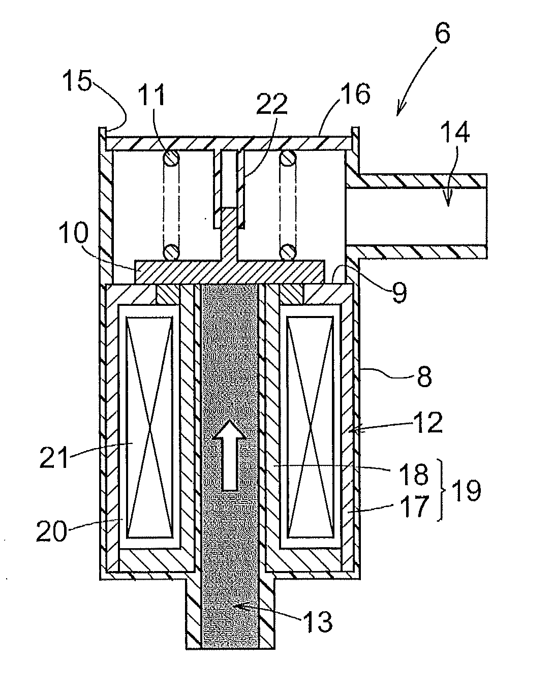
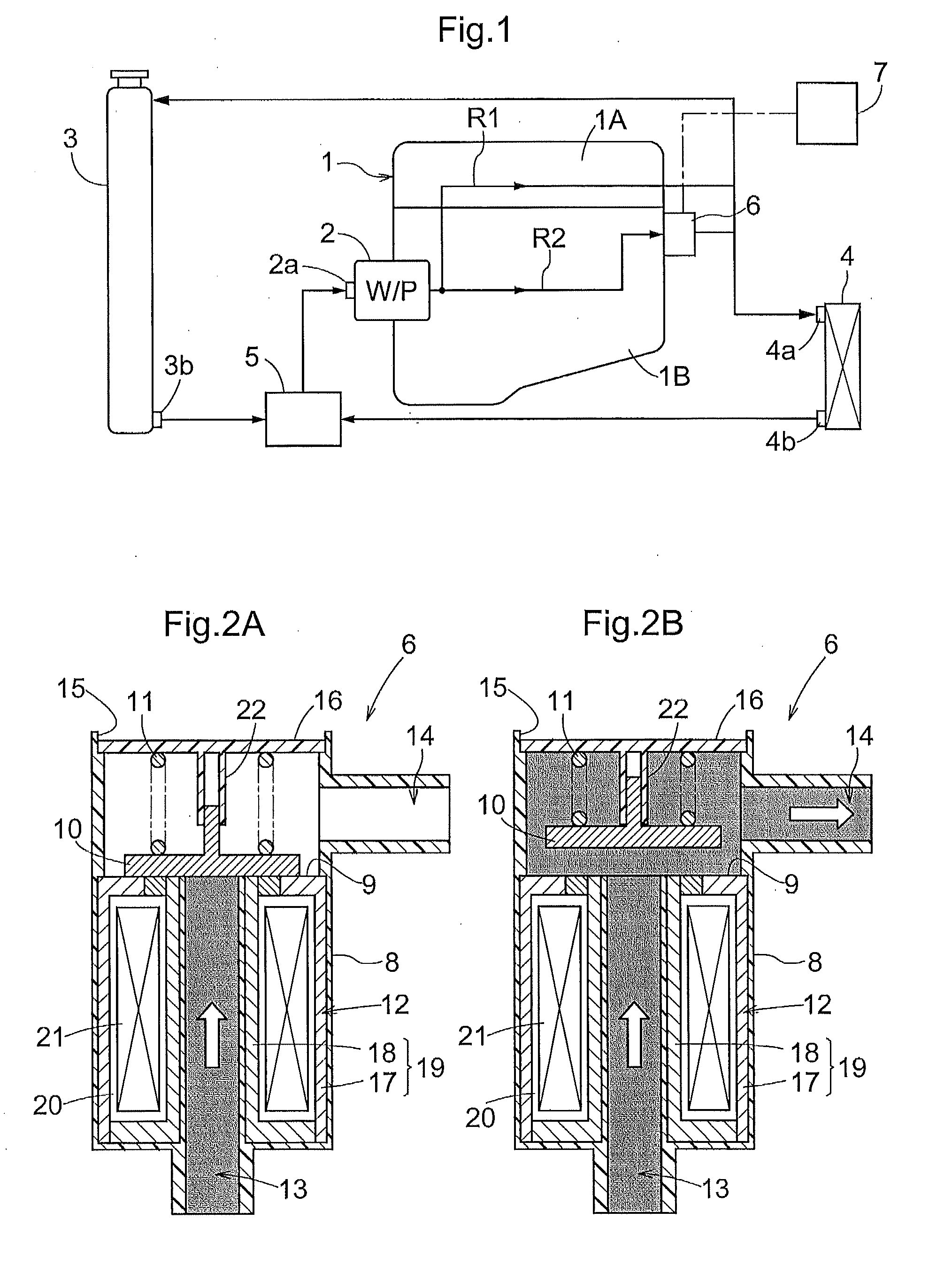
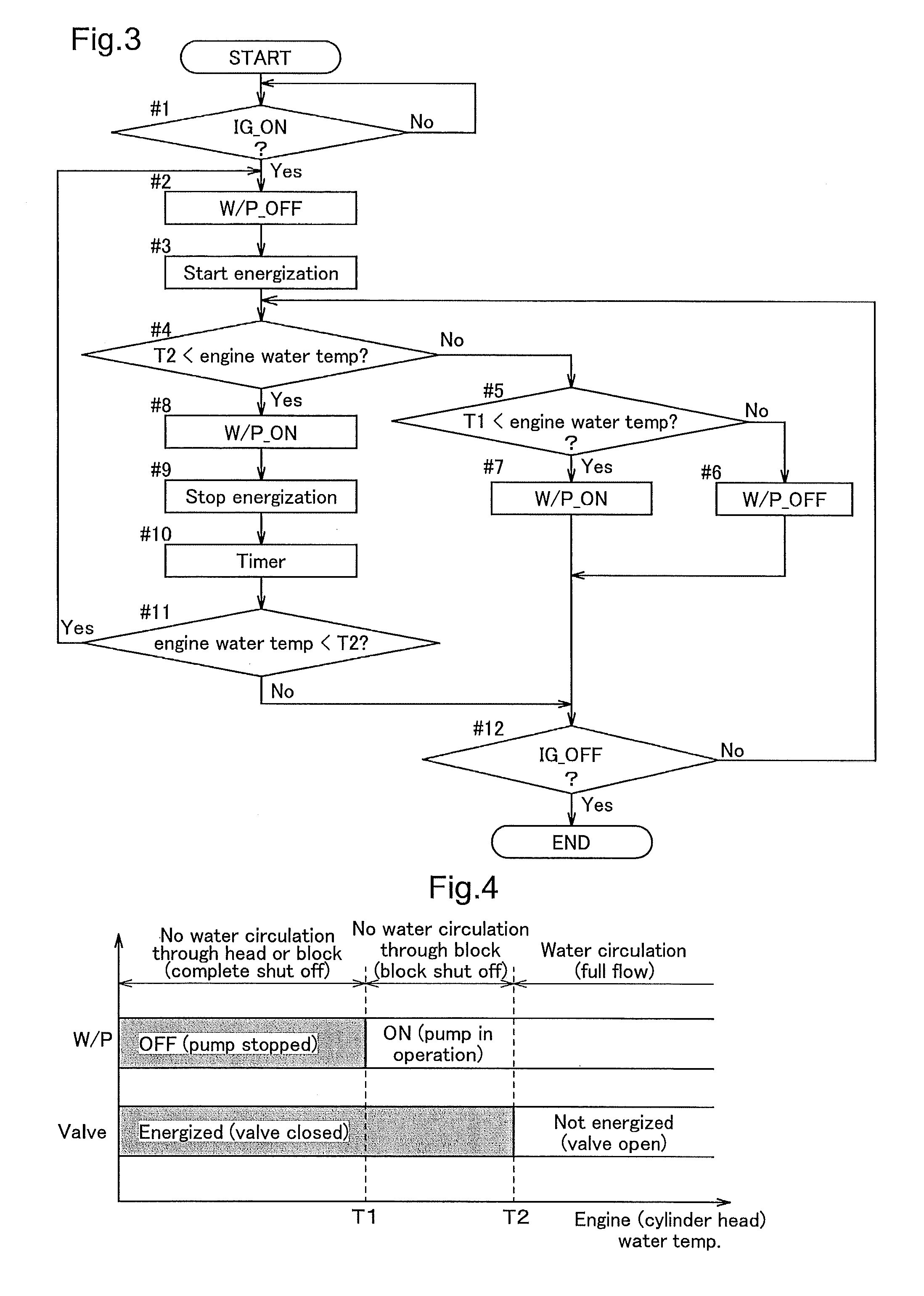
[0051]FIG. 5 is a flowchart showing the control operation performed according to another embodiment of the present invention. This embodiment differs from Embodiment 1 in omitting the step of predetermined time lapse processing after the determination by the control unit 7 at Step #4 that the engine temperature is above T2 (Yes) to subsequently place the water pump 2 in operation and stop energizing the solenoid 12 (Steps #8 and #9).

[0052]According to this embodiment, if it is determined at Step #10 that the engine water temperature is above T2 (No) and if it is determined at Step #11 that the ignition is turned on, the process returns immediately upstream of Step #8, subsequently repeating Steps #8, #9, #10, and #12 unless the engine water temperature falls below T2. If the engine water temperature falls below T2, it is determined at Step #10 that the engine water temperature is below T2 (Yes) (i.e., it is determined that conditions are ready for stopping the coolant circulation th...

embodiment 3

[0053]FIG. 6 is a flowchart showing the control operation performed according to still another embodiment of the present invention. Also in this embodiment, the control unit 7 determines at Step #4 that the engine water temperature is above T2 (Yes) to subsequently place the water pump 2 in operation and stop energizing the solenoid 12 (Steps #8 and #9), and after that the control unit 7 also determines at Step #11 that the engine water temperature is above T2 (Yes). The present embodiment differs from Embodiment 1 in that the process following Step #11 is carried out in a separate routine.

[0054]If it is determined at Step #11 that the engine water temperature is below T2 (Yes) (i.e., it is determined that conditions are ready for stopping the coolant circulation through the second circulation path R2), the water pump 2 is stopped (Step #12) and energization of the solenoid 12 is started (Step #13) to close the solenoid valve 6. After a lapse of a predetermined time (Step #14), the ...


PUM


Abstract

A vehicle cooling device includes a pump, circulation paths connected to the pump for circulating coolant between a cooling object and a heat exchanger, a solenoid valve for opening and closing at least one of the circulation paths, and a control unit for controlling pump operation. The solenoid valve includes a valve body movable between a position separated from a valve seat and a position abutting the valve seat, the valve body being held in abutment with the valve seat, and a solenoid maintaining the abutment when energized. The valve body allows coolant fluid pressure to move the valve body separate from the valve seat when the solenoid is not energized and the pump is in operation, and the control unit performs controlling to stop the pump and start solenoid energization when conditions are ready for stopping coolant circulation through the circulation path in which the solenoid valve is disposed.

Description

TECHNICAL FIELD[0001]The present invention relates to a vehicle cooling device for use with the cooling system for an engine or the like.BACKGROUND ART[0002]A vehicle cooling device includes, for example, an electric pump, an engine as an object of cooling, a heat exchanger, a circulation path for circulation of coolant between the engine and the heat exchanger by the operation of the pump, and a solenoid valve capable of opening and closing the circulation path. This solenoid valve may be of the type in which the valve body is brought into abutment with the valve seat by the biasing force of a biasing member when the solenoid is not energized to switch the valve to a closed state, and the valve body is moved against the biasing force of the biasing member by the energization of the solenoid to switch the valve to an open state (see, for example, Patent Document 1). Accordingly, in order to circulate the coolant between the object of cooling and the heat exchanger, it is necessary t...

Claims


Application Information

Patent Timeline
IPC IPC(8): F01P7/00
CPCF16K15/028F16K15/18F16K31/0658F01P2003/027F16K31/0651F01P7/167F01P2005/125F01P2007/146F01P7/00F01P5/12
Inventor MATSUSAKA, MASANOBUSATO, TADAYOSHITAKANO, HIROHISA
Owner AISIN SEIKI KK
Why Eureka
Try Eureka