Medium stocking apparatus

a technology for stocking equipment and medium-sized containers, which is applied in the direction of pile separation, transportation and packaging, instruments, etc., can solve the problems of tape being torn off, troublesome maintenance work, and increasing the diameter of the tap

Active Publication Date: 2013-09-19
OKI ELECTRIC IND CO LTD
View PDF2 Cites 4 Cited by
  • Summary
  • Abstract
  • Description
  • Claims
  • Application Information

AI Technical Summary

Benefits of technology

[0011]The present invention can provide the medium stocking apparatus that blocks up, during a normal operation, the open area of the wrapping guide to protect the internal space of the housing, and opens, during the maintenan...

Problems solved by technology

With the above configuration, there is a possibility that a damaged bill is torn off and a chip of the bill (hereafter called as stub) gets into an unintended place in the housing of the temporary holding section, or that a lot of bills is wrapped around the drum, which becomes increasing its diameter, and as a consequence the drum comes into contact with a movable guide so as to be disabled to rotate to discharge bills.
Such a maintenance work is troublesome because the movable guide cannot widely be opened up due to the s...

Method used


Image

  • Medium stocking apparatus
  • Medium stocking apparatus
  • Medium stocking apparatus

Examples


first embodiment

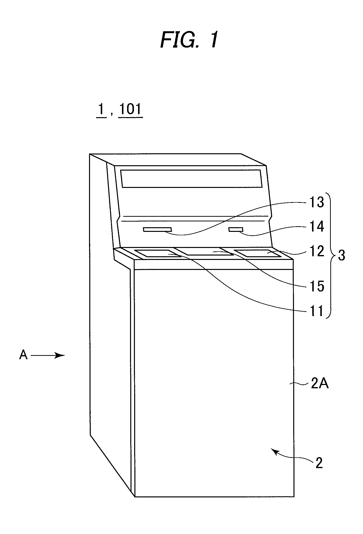
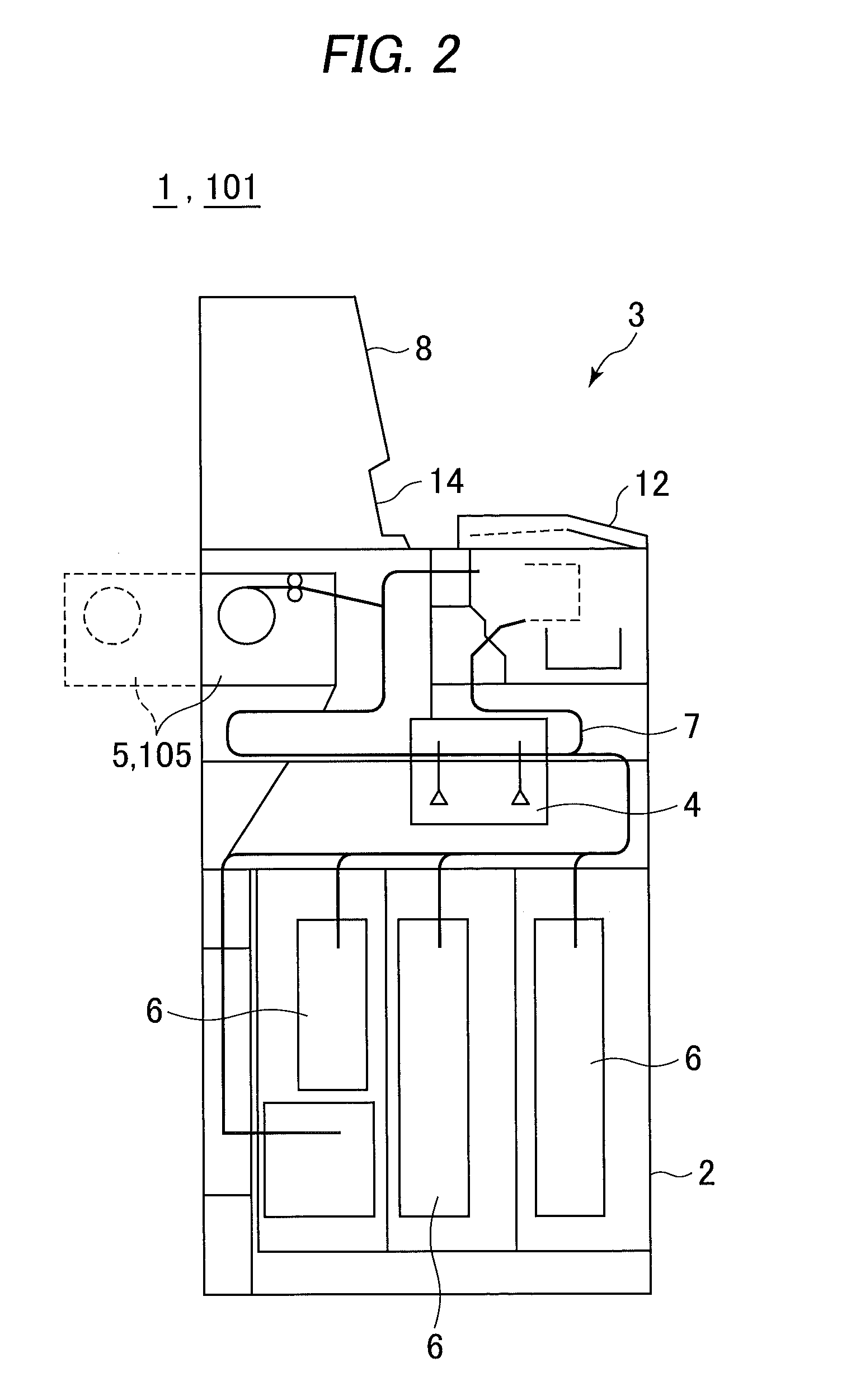
[0023]With reference to the accompanying drawings, the entire structure of a medium stocking apparatus according to the present invention will be described in detail. As shown in FIG. 1, an automated teller machine 1 is elementally constructed by a housing 2 to be served to conduct cash transactions with customers. The housing 2 is provided with a customer service section 3 in an area convenient for the customer standing in front of the machine to insert bills into the machine and operate its touch panel, i.e. an area across from the upper part of its foreside 2A to its top side.

[0024]The customer service section 3 is designed to directly handle cash, a bankbook and the like for the customer as well as imparting information on a transaction and receiving operational instructions, and is provided with a coin slot 11, a bill slot 12, a bankbook slot 13, a card slot 14 and a display console 15.

[0025]The coin slot 11 and the bill slot 12 are adapted for receiving coins and bills the cus...

second embodiment

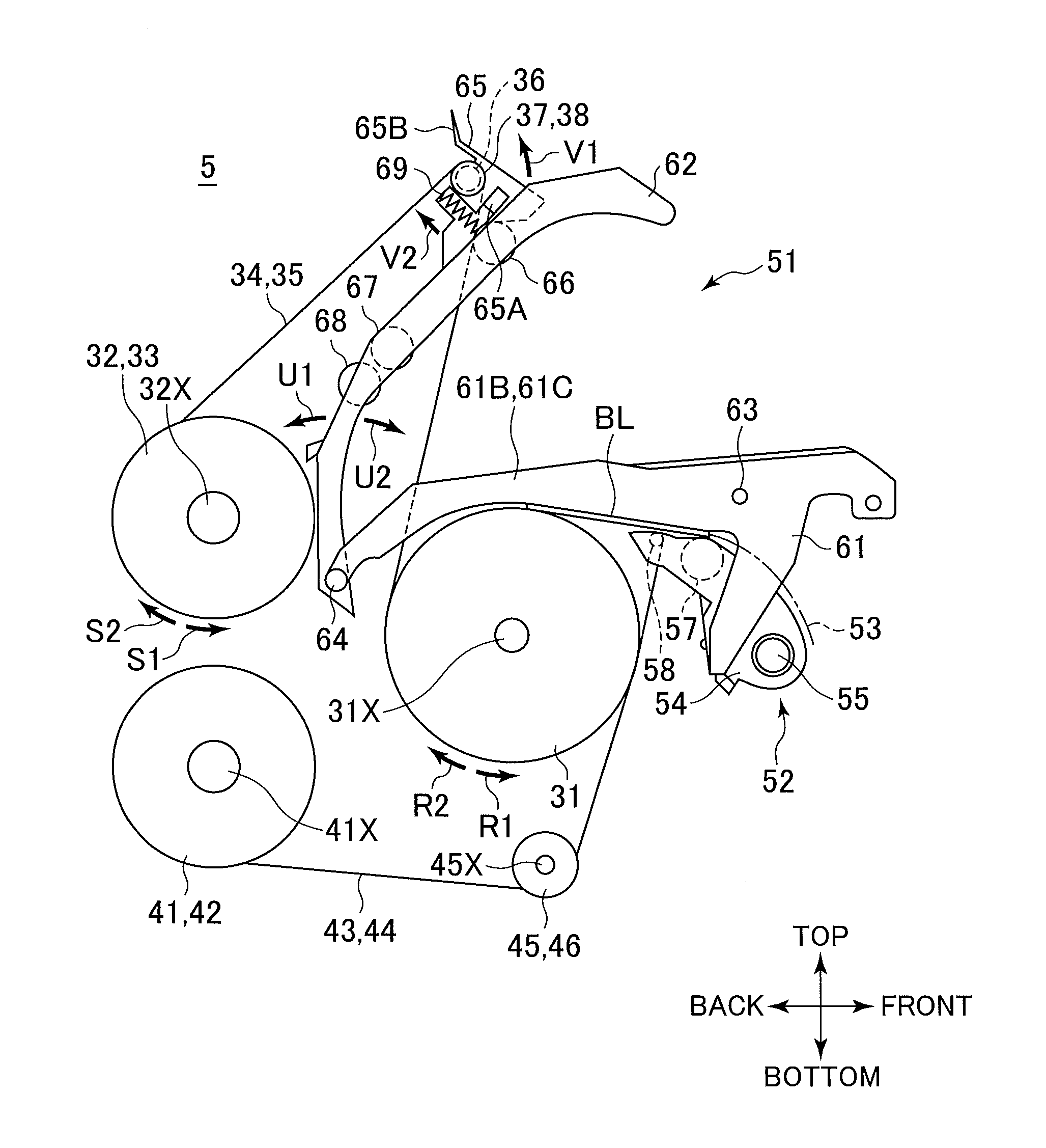
[0117]Specifically, the movable upper guide 151 of the second embodiment is arranged so that, as illustrated in FIG. 9, the upper guide base 162 lying anterior to the place contacting with the drum 31 can rotate in the open direction U1 with the upper drum guide 163 retained.

[0118]Furthermore, the upper guide base 162 is provided with the conveyance rollers 66, 67 and 68 on its under surface as with the upper guide base 62, and above the front side of the guide base 162 the pulley shaft 36, the upper tape pulleys 37, 38 and the lock lever 65 are fitted.

[0119]The above configuration can produce the following advantages.

[0120]In the temporary holding section 105 according to the second embodiment, the frame 161 and the upper guide base 162 are rotatably joined by the retraction shaft 64 in the vicinity of the upper part of the place where the movable upper guide 151 comes in contact with the drum 31, and as in the case with the first embodiment, the engagement groove 65A of the lock l...


PUM


Abstract

A medium stocking apparatus includes a housing having an open area, reels on which tapes are wound, a diverting unit for turning backward the tapes, a cylindrical drum on which a medium is wound with the tapes overlaid, and an openable unit for closing and opening an internal space from and to outside. During an operation, a closed state can be retained, and, during a maintenance work, an open state can be achieved, in which the openable unit is rotated in an upward direction for displacing upper tapes. The medium stocking apparatus can thus be offered which allows a maintenance work with high workability without impairing the tapes.

Description

TECHNICAL FIELD[0001]The present invention relates to a medium stocking apparatus, which is preferably applied to an automated teller machine (ATM) for putting media such as bills into the machine to conduct a desired transaction.BACKGROUND ART[0002]Consumer transaction facilities, e.g. automated teller machines, have been used in, e.g. financial institutions to carry out transactions with customers, e.g. transactions of depositing cash, namely bills and coins, or withdrawing cash by a customer.[0003]Japanese patent laid-open publication No. 2011-2921 offers an automated teller machine, which includes a bill slot for giving and receiving bills to and from a customer, a validator for determining the denominations and authenticity of bills deposited in the machine, a temporary holding section for temporarily holding deposited bills, and denomination-sorted cassettes for stocking bills sorted by denominations. In the automated teller machine, when the customer inserts bills into the bi...

Claims


Application Information

Patent Timeline
IPC IPC(8): G07D11/00
CPCB65H5/28G07D11/0021B65H29/006B65H2402/441B65H2601/321G07D11/0081B65H2301/41912B65H2402/64B65H2701/1912G07D11/40B65H2402/60G07D11/16
Inventor KASHIWABUCHI, MASASHIIWATSUKI, KEISUETAKA, MICHIOHATA, NAOKI
Owner OKI ELECTRIC IND CO LTD
Why Eureka
Try Eureka