Wire electrical discharge machining device

a wire electrode and machining technology, applied in the direction of manufacturing tools, electrical-based machining electrodes, electric circuits, etc., can solve the problems of wire electrode breakage, unduly large energy, and achieve the effect of effective prevention of wire breakage and improvement of material removal ra

Active Publication Date: 2013-09-19
SODICK CO LTD
View PDF124 Cites 15 Cited by
  • Summary
  • Abstract
  • Description
  • Claims
  • Application Information

AI Technical Summary

Benefits of technology

[0014]The wire electrical discharge machining device of the present invention calculates the allowed tension based on the wire breaking tension at which the wire electrode breaks, and changes the set tension to the allowed tension; therefore, wire breakage can be effectively prevented. In addition, energy for electrical discharge machining is not necessary to be unduly limited from the point of view of the wire breakage; therefore, a material removal rate can be improved.

Problems solved by technology

However, an unduly large tension may cause undesirable breakage (wire breakage) of the wire electrode.
Unduly large energy for electrical discharge machining is also easy to cause wire breakage.

Method used


Image

  • Wire electrical discharge machining device
  • Wire electrical discharge machining device
  • Wire electrical discharge machining device

Examples


Embodiment Construction

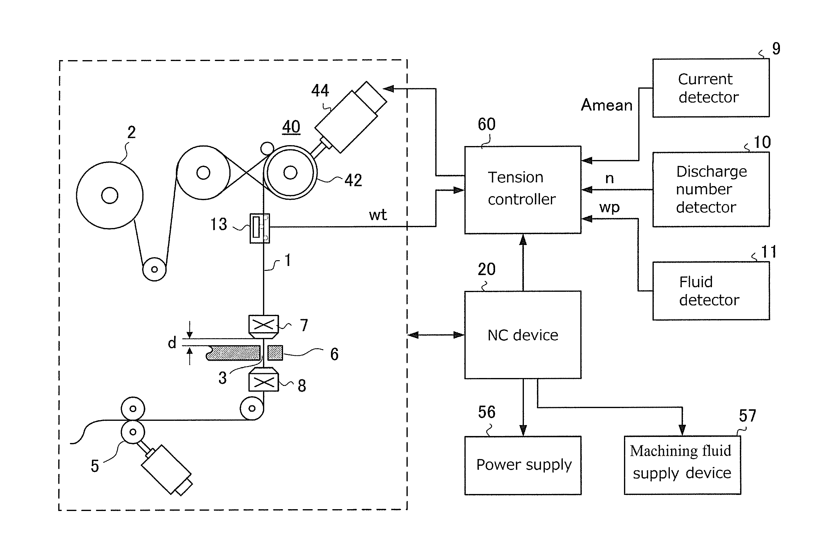
[0021]Referring to FIG. 1, a wire electrical discharge machining device of the present invention is described. A wire electrode 1 is transported from a wire reel 2 to a pulling device 5 via a wire transportation path. A tension applying device 40, a tension detector 13, a pair of nozzles 7, 8 and a plurality of pulleys are located on the wire transportation path. The tension applying device 40 applies a tension for maintaining a straightness of the wire electrode 1 to the wire electrode 1. The tension applying device 40 includes a break pulley 42 to provide a friction to the wire electrode 1 and a servomotor 44 connected to the break pulley 42. The tension detector 13 comprises, for example, a strain gauge, and located between the break pulley 42 and the upper side nozzle 7.

[0022]The nozzles 7, 8 for injecting a machining fluid to a work 6 are located above and below with the work 6 therebetween. A machining gap 3 is formed between the wire electrode 1 and the work 6. In high-speed ...


PUM

PropertyMeasurementUnit
timeaaaaaaaaaa
tensionaaaaaaaaaa
breaking tensionaaaaaaaaaa

Abstract

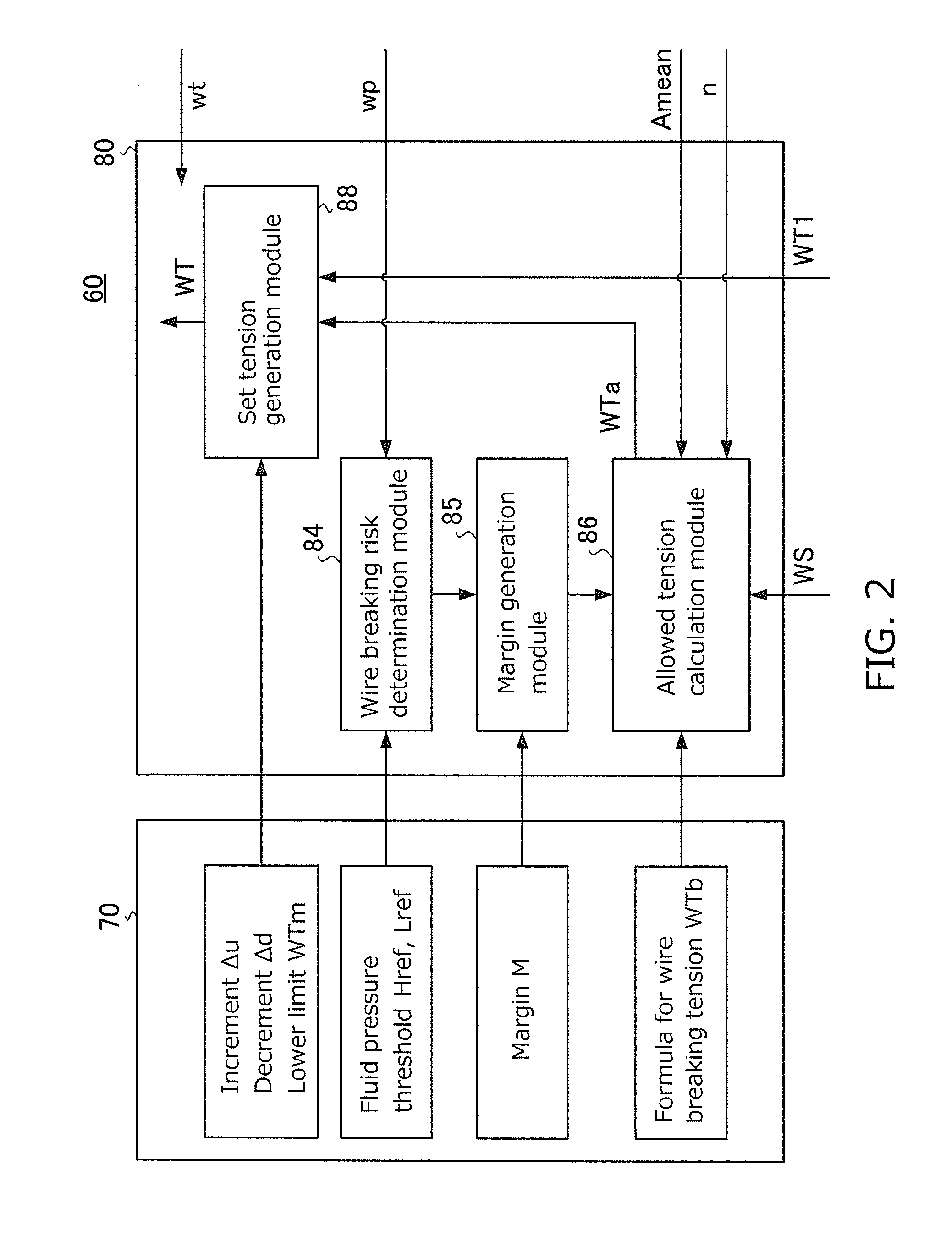
Provided is a wire electrical discharge machining device which has a tension controller for maintaining the tension of a traveling wire electrode at a tension. The tension controller includes: an allowed tension calculation module for determining an allowed tension that is less than a wire breaking tension at which the wire electrode breaks; and a set tension generation module for generating the set tension in accordance with the allowed tension. When the set tension is greater than the allowed tension, the set tension generation module reduces the set tension. When the set tension is less than the allowed tension, the set tension generation module increases the set tension in such a way that the set tension does not exceed the allowed tension.

Description

TECHNICAL FIELD[0001]The present invention relates to a wire electrical discharge machining device for machining a work by generating electrical discharge in a gap (“machining gap”) formed between a wire electrode and the work. In particular, the present invention relates to a wire electrical discharge machining device for controlling a tension applied to a wire electrode traveling along a wire transportation path.BACKGROUND TECHNIQUE[0002]In general, during machining, a wire electrode is transported between a pair of wire guides in a direction substantially vertical to XY plane while moving relatively to a work within XY plane. The travelling vertical wire electrode is a tool for electrical discharge machining. A machining fluid, such as water with high specific resistance, is supplied to a machining gap. In order to generate one electrical discharge for a predetermined duration (“ON time”), a voltage pulse is applied to the machining gap. A current flows through the machining gap ...

Claims


Application Information

Patent Timeline
Patent Type & Authority Applications(United States)
IPC IPC(8): B23H7/10
CPCB23H1/02B23H7/104
Inventor YAMADA, KUNIHARUKOUGO, MASAKIYANAGISAWA, TOMOYUKI
Owner SODICK CO LTD
Why Eureka
Try Eureka