

Vehicle pillar structure
- Summary
- Abstract
- Description
- Claims
- Application Information
AI Technical Summary
Benefits of technology
Problems solved by technology
Method used
Image

Examples
first embodiment
[0043
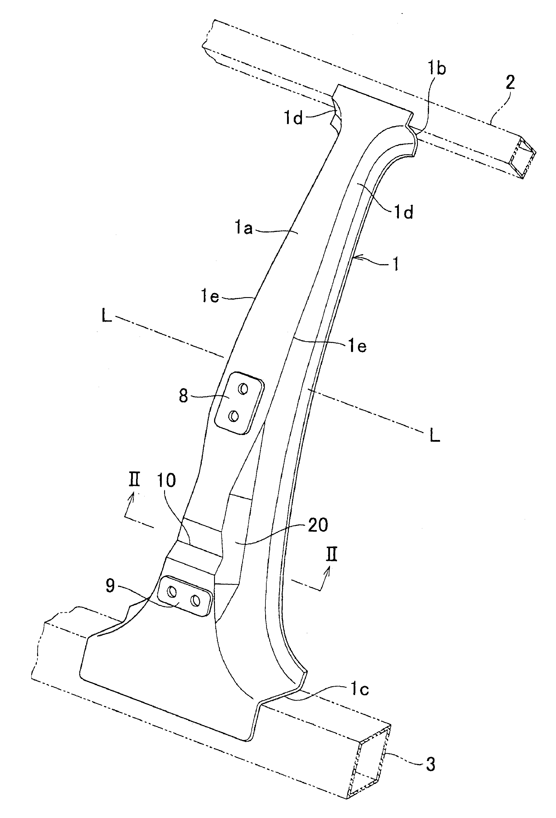
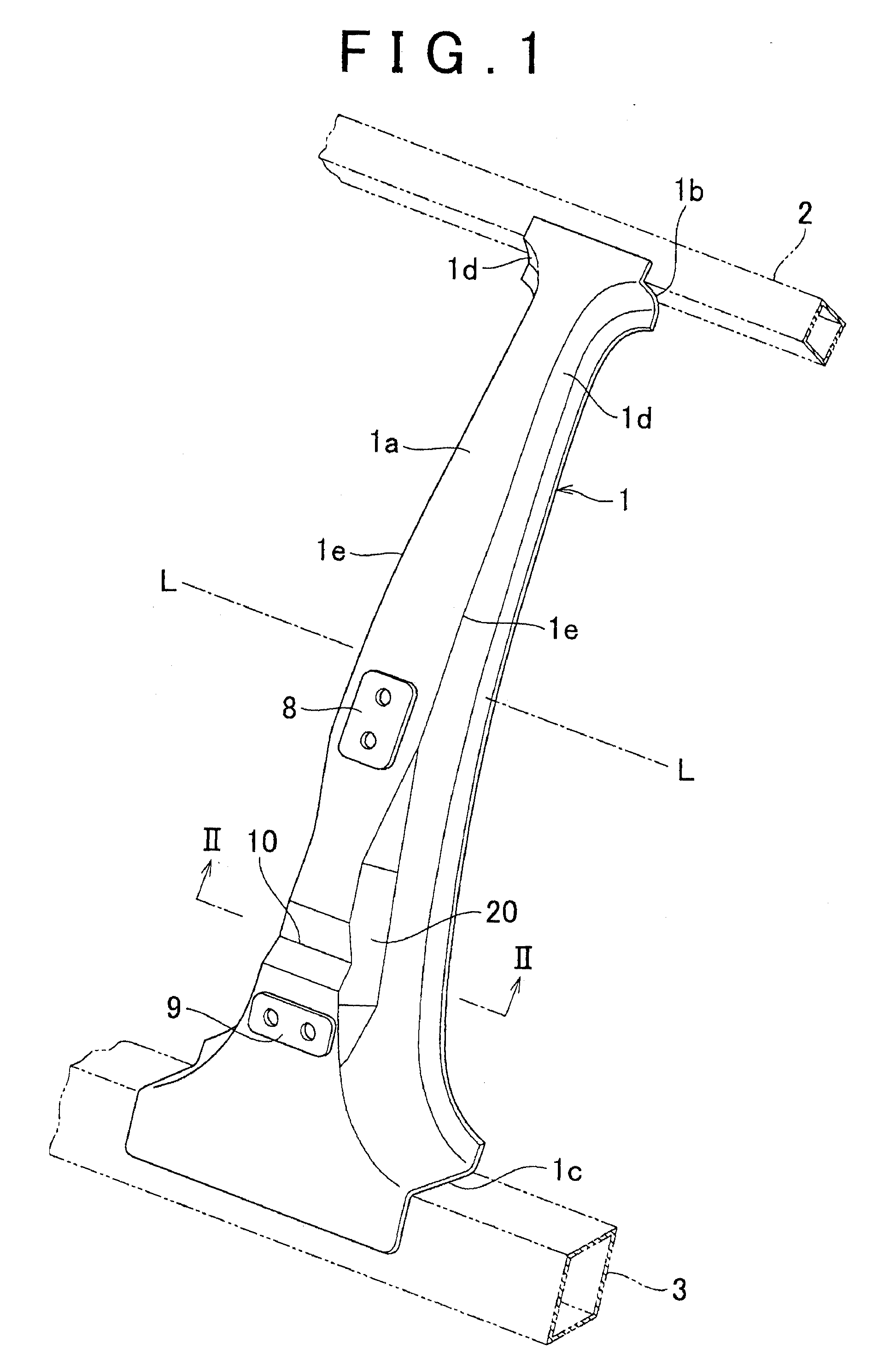
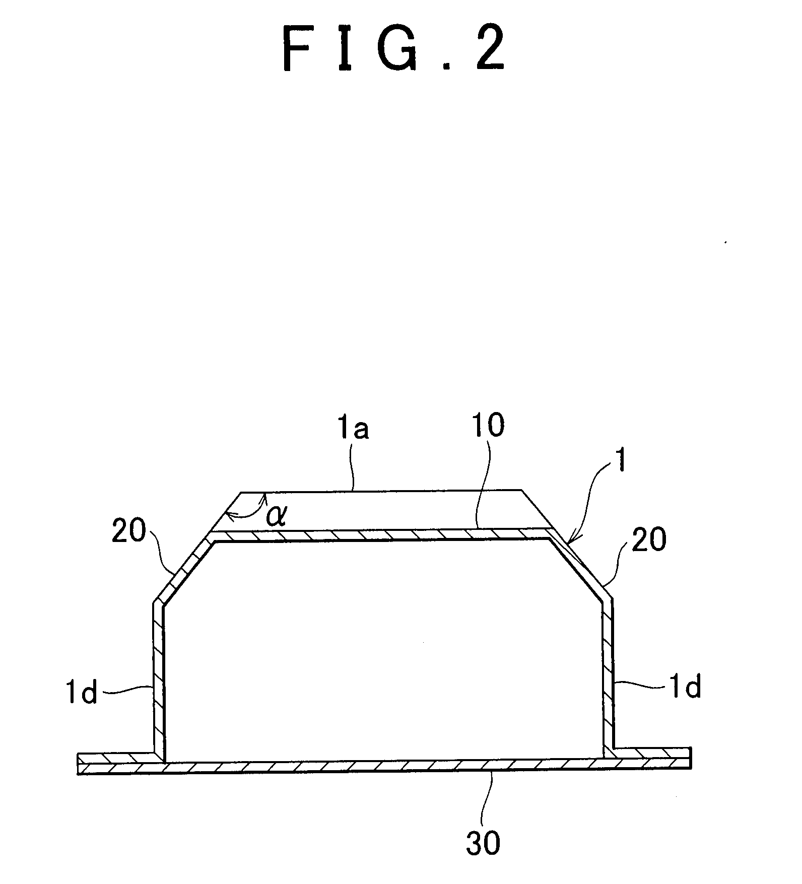
[0044]As shown in FIG. 1 and FIG. 2, a reinforcement 1 of a center pillar (B pillar) extends between a roof side rail 2 and a rocker 3, as shown in FIG. 1 and FIG. 2. An upper portion of the reinforcement 1 is provided with an upper attachment portion 1b for welding the reinforcement 1 to the roof side rail 2. A lower portion of the reinforcement 1 is provided with a lower attachment portion 1c for welding the reinforcement 1 to the rocker 3.
[0045]Furthermore, the reinforcement 1 is provided with an upper hinge seat portion 8 and a lower hinge seat portion 9 to which the hinges of a door are fixed. In the center pillar, an outer surface of the reinforcement 1 constructed as described above is covered with a side outer panel (not shown).
[0046]A front pillar (A pillar) serves to support a vehicle cabin in the event of a head-on collision or an offset collision. On the other hand, the center pillar serves to support the vehicle cabin in the event of a side collision. When a side c...
second embodiment
[0052
[0053]As shown in FIG. 3 and FIGS. 4A and 4B, an obverse face 1a of a reinforcement 1A of a center pillar has beads (buckling portions) 11A and 11B, which are provided in the stated order from above between the upper hinge seat portion 8 and the lower hinge seat portion 9. Both of the upper hinge seat portion 8 and the lower hinge seat portion 9 are positioned below the beltline L. The beads 11A and 11B each form a V-shape groove that extends in the lateral direction of the reinforcement 1A, and the groove of the bead 11B has a greater depth than the groove of the bead 11A. As for the beads of this kind, the deeper the groove is, the lower the buckling strength is. Therefore, the buckling strength of the bead 11B is lower than the buckling strength of the bead 11A. The beads 11A and 11B serve as starting points when the reinforcement 1A buckles in response to an external force.
[0054]Beads 40A, 40B and 40C are formed in the side face 1d on each side of the obverse face 1a. The b...
third embodiment
[0063
[0064]As shown in FIG. 5 and FIGS. 6A and 6B, an obverse face 1a of a reinforcement 1B of a center pillar has beads (buckling portions) 11A and 11B, which are provided in the stated order from above between the upper hinge seat portion 8 and the lower hinge seat portion 9. Both of the upper hinge seat portion 8 and the lower hinge seat portion 9 are positioned below the beltline L. The groove of the bead 11B has a greater depth than the groove of the bead 11A. Therefore, the buckling strength of the bead 11B is lower than the buckling strength of the bead 11A. The beads 11A and 11B serve as starting points when the reinforcement 1A buckles in response to an external force.
[0065]Beads 40A, 40B and 40C are formed in the side face 1d on either side of the obverse face 1a. Accordingly, each of the side faces 1d is divided into side faces 50A, 50B, 50C and 50D.
[0066]Strain reducing face portions 22 are formed on two ridge portions 1e positioned at both sides of the obverse face 1a o...
PUM
 Abstract
Description
Claims
Application Information