Pen type coordinate indicator

a technology of coordinate indicators and pen pressures, applied in the field of pen pressure indicators, can solve problems such as erroneous detection of pen pressures

Active Publication Date: 2013-09-19
WACOM CO LTD
View PDF2 Cites 14 Cited by
  • Summary
  • Abstract
  • Description
  • Claims
  • Application Information

AI Technical Summary

Benefits of technology

[0029]In addition, after the distance between the end surfaces of the first and second magnetic bodies facing each other has reached the predetermined distance value, in addition to the first elastic body, the second elastic body is elastically deformed, and thus the distance between the end surfaces of the first and second magnetic bodies facing each other is further narrowed. At this point, when the distance between the end surfaces of the first and second magnetic bodies facing each other becomes shorter (narrower) than the predetermined distance value, the inductance value of the coil is changed mainly at the sensitivity corresponding to the second elastic body, whereby it is possible to change the phase (frequency) of the electric wave to be transmitted.

Problems solved by technology

Specifically, in the case of the conventional pen type coordinate indicator 100, it is possible that even when the conventional pen type coordinate indicator 100 is merely inclined (or tilted) with respect to the position detector 200, the inductance value of the coil 105 is changed and thus the phase of the electric wave transmitted from the pen type coordinate indicator 100 is changed, which leads to erroneous detection of a pen pressure.
In this case, the phase of the electric wave supplied from the pen type coordinate indicator 100 is changed, which may lead to erroneous detection of a pen pressure.

Method used


Image

  • Pen type coordinate indicator
  • Pen type coordinate indicator
  • Pen type coordinate indicator

Examples


Embodiment Construction

[0043]A pen type coordinate indicator according to an embodiment of the present invention will be described in detail hereinafter with reference to the accompanying drawings.

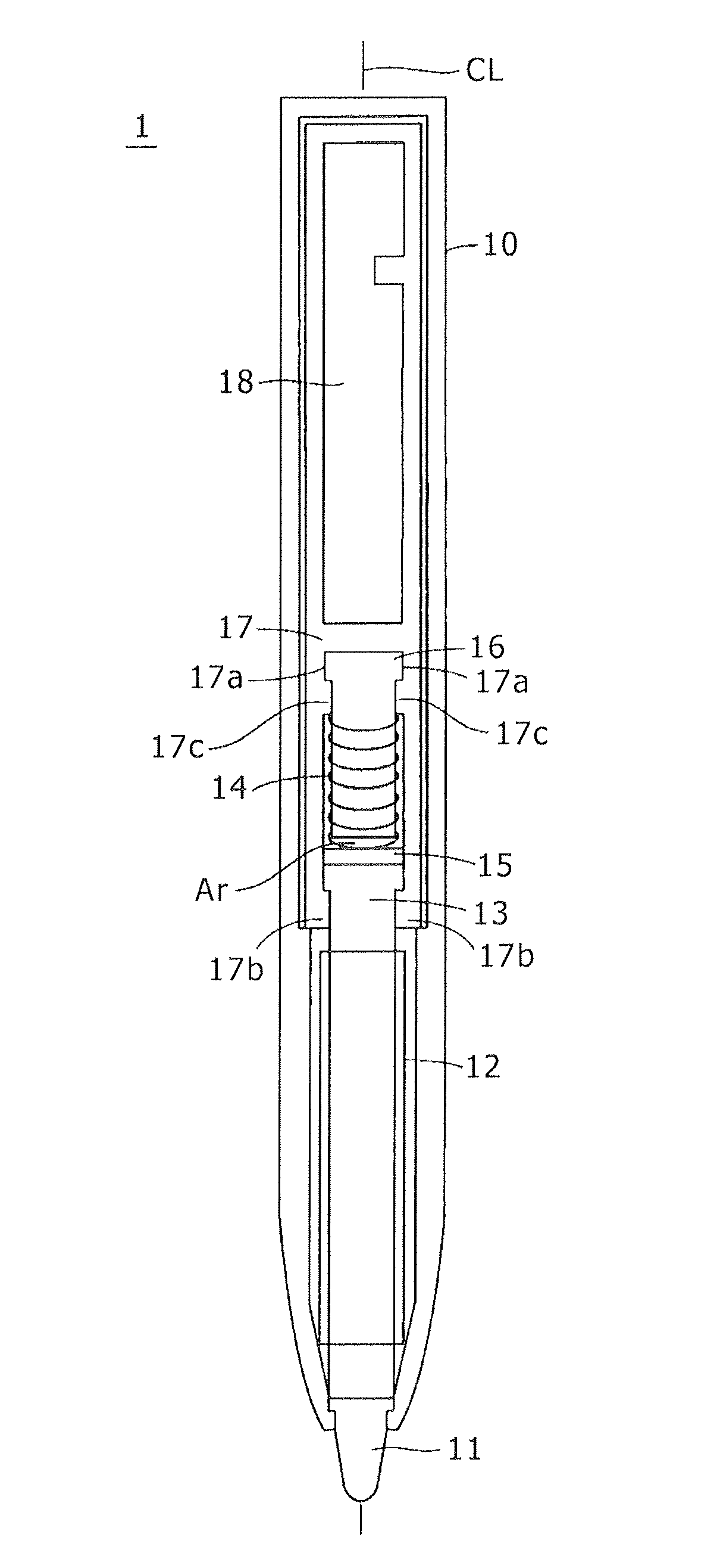
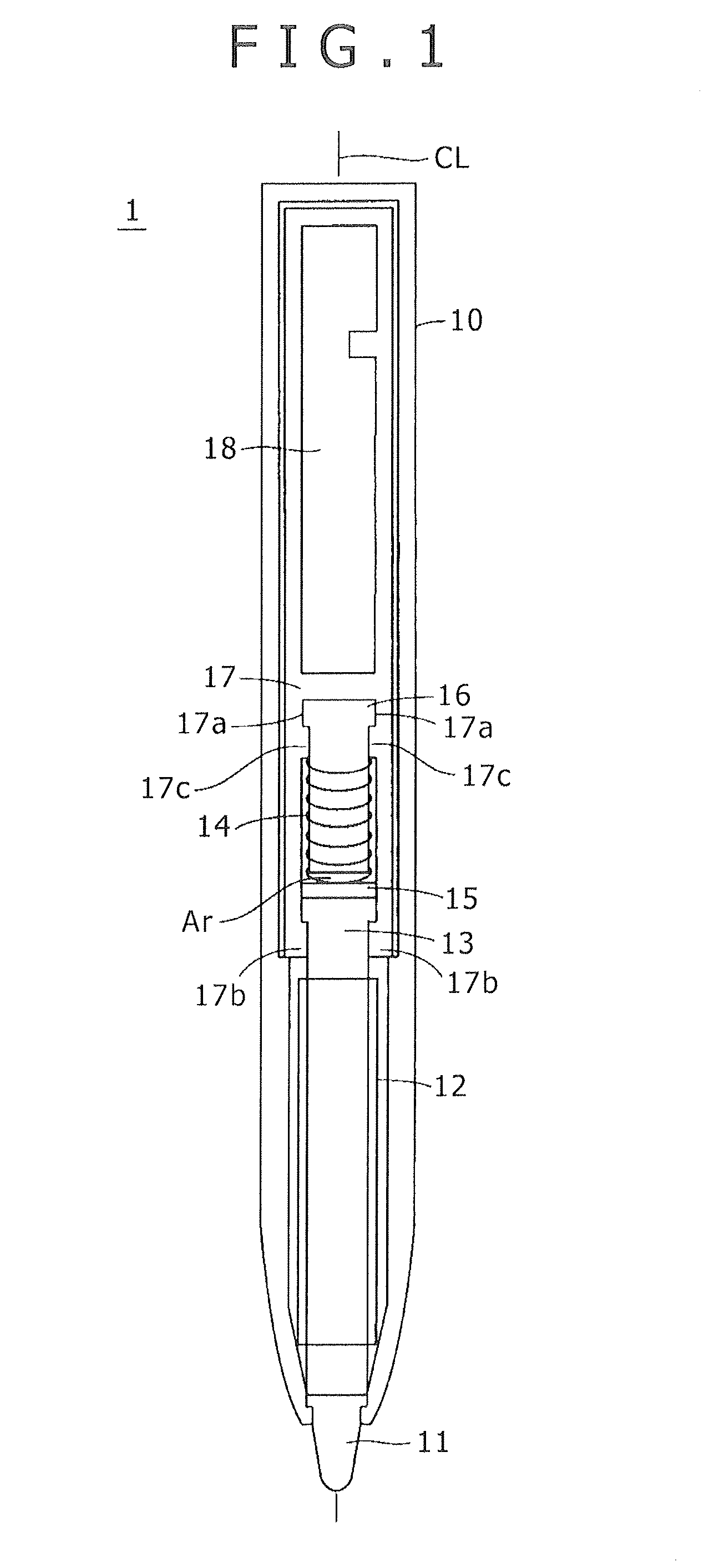
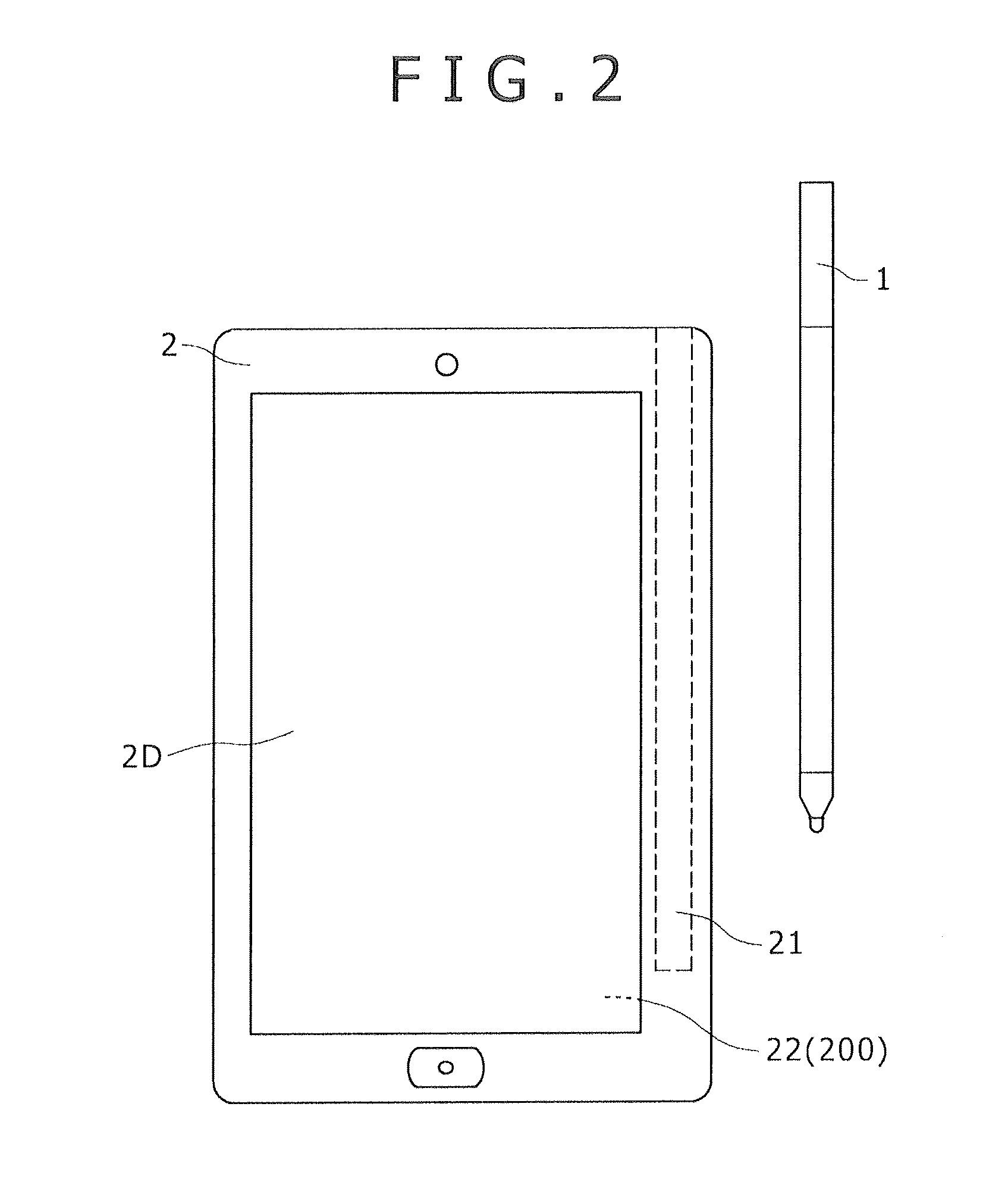
[0044]FIG. 1 is a view illustrating a structure of a pen type coordinate indicator 1 according to an embodiment of the present invention. FIG. 2 is a top plan view illustrating an example of an electronic apparatus 2 that includes the pen type coordinate indicator 1 according to the present embodiment. In the case shown in FIG. 2, the electronic apparatus 2 is, for example, a high-performance cellular phone unit including a display screen 2D of a display device such as a Liquid Crystal Display (LCD) device. The electronic apparatus 2 includes an electromagnetic induction type position detector 22 on the back side of the display screen 2D. The electromagnetic induction type position detector 22 is configured similarly to the conventional position detector 200, which was described with reference to FIG. 10.

[0045]A...


PUM


Abstract

A pen type coordinate indicator for a position input device is provided, which is capable of widening a detection range of a pressing pressure (pen pressure) while preventing erroneous (false) detection. A coil spring (i.e., a first elastic body) and a silicon rubber (i.e., a second elastic body) are interposed between an end surface of a first ferrite core, around which a coil connected to a resonance circuit is wound, and an end surface of a second ferrite core, within the pen. The first and second elastic bodies operate to controllably change (narrow) the distance between the two end faces in accordance with the pressure applied to the pen tip. As a result, an inductance value of the coil wound around the first ferrite core is controllably changed and thus a phase (frequency) of an electric wave transmitted from the resonance circuit to a position detector is controllably changed.

Description

CROSS-REFERENCE TO RELATED APPLICATION(S)[0001]The present application claims priority under 35 U.S.C. 119(a) of Japanese Application No. 2012-058712, filed Mar. 15, 2012, the entire content of which is incorporated herein by reference.BACKGROUND[0002]1. Technical Field[0003]The present invention relates to a pen type coordinate indicator, which indicates a position to be detected to a position detector for detecting an indicated position, and which supplies information corresponding to a user operation.[0004]2. Description of the Related Art[0005]In recent years, a position input device has been used as an input device for a tablet type Personal Computer (PC) or the like. The position input device is composed, for example, of a coordinate indicator formed in a pen shape (pen type coordinate indicator), and a position detector having an input surface on which a pointing operation and other operations to input characters, drawings, or the like, are carried out by using the pen type c...

Claims


Application Information

Patent Timeline
Patent Type & Authority Applications(United States)
IPC IPC(8): G06F3/0354
CPCG06F3/03545G06F3/046G06F3/033
Inventor FUKUSHIMA, YASUYUKIFUJITSUKA, HIROYUKI
Owner WACOM CO LTD
Why Eureka
Try Eureka