Protective device for protection of an electrical circuit against reversal of polarity, method, circuit arrangement and vehicle system

Active Publication Date: 2013-09-19
BROSE FAHRZEUGTEILE GMBH & CO KG HALLSTADT (DE)
View PDF3 Cites 1 Cited by
  • Summary
  • Abstract
  • Description
  • Claims
  • Application Information

AI Technical Summary

Benefits of technology

The present invention aims to offer a simplified solution for protecting electrical circuits from voltage reversal. The technical effect of this invention is to minimize the impact of voltage reversal on electrical circuits.

Problems solved by technology

In particular in electrical circuits which are operated with a d.c. voltage, if the input voltage is supplied with incorrect polarity to an electrical circuit this may lead not only to a malfunction of the electrical circuit but also to the destruction of electrical or electronic components of the electrical circuit.
However, a disadvantage of the use of diodes as protection against reverse polarity is that there is a power loss in the diodes and a voltage drop occurs on each of the diodes.
This leads to a deterioration in the efficiency of the electrical circuit.
This means that the electrical circuit is disconnected when its function is not used.
In this way the MOSFET which serves for protection of the electrical circuit is prevented from overloading in the event of a suddenly reversal of polarity of the electrical input voltage by an electrical current flowing out of the electrical circuit, so that this may become incapable of functioning.
If the MOSFET were disconnected at this moment in order to prevent damage to the electrical circuit, the MOSFET would be destroyed because of the high current to be switched.
However, a disadvantage of P-channel MOSFETs is that whilst they have the same power as a comparable N-channel MOSFET they must have significantly larger dimensions and therefore are also substantially more expensive.
However, such a protection against reverse polarity cannot be used because this supply branch usually also constitutes the earth connection the electronic circuit.
However, if this supply line is not interrupted regularly, in the event of a suddenly reversal of polarity of the input voltage the electrical circuit of the N-channel MOSFET is overloaded.

Method used


Image

  • Protective device for protection of an electrical circuit against reversal of polarity, method, circuit arrangement and vehicle system
  • Protective device for protection of an electrical circuit against reversal of polarity, method, circuit arrangement and vehicle system
  • Protective device for protection of an electrical circuit against reversal of polarity, method, circuit arrangement and vehicle system

Examples


Embodiment Construction

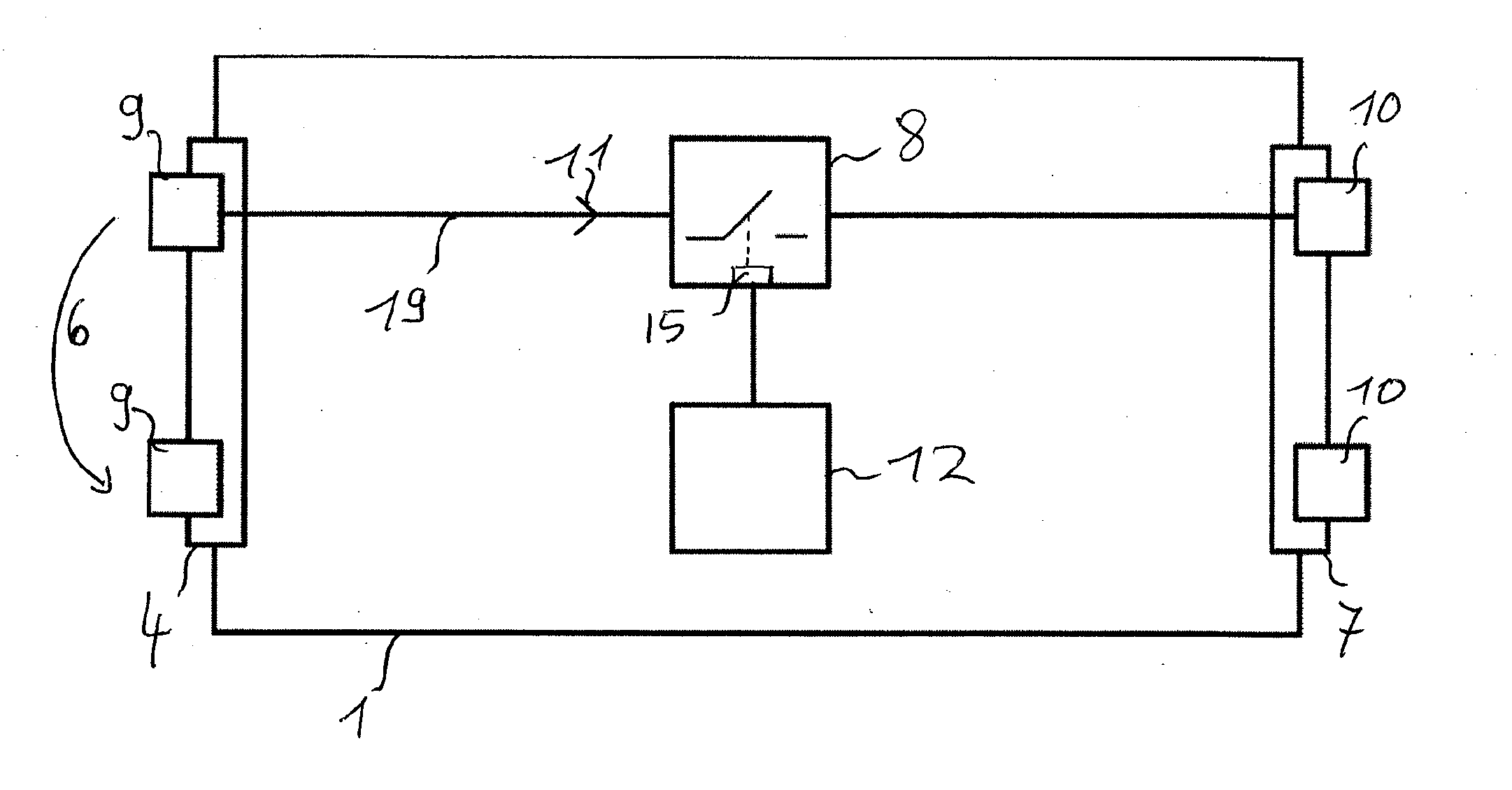
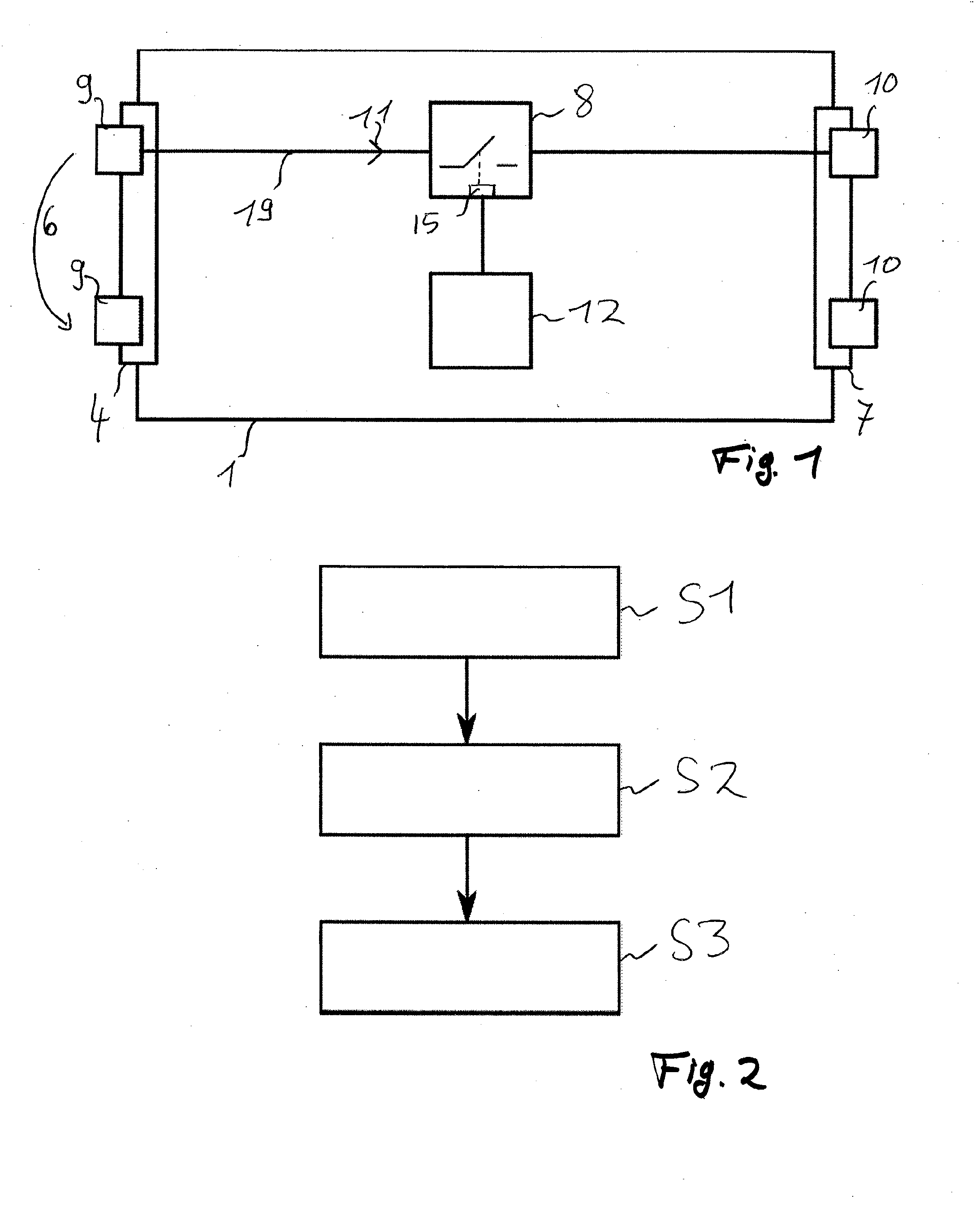
[0043]FIG. 1 shows a block diagram of an embodiment of a protective device 1 according to the invention.

[0044]The protective device 1 has an input 4 which has two input terminals 9. The protective device 1 also has an output 7 which has two output terminals 10. One of the input terminals 9 is designed to be coupled to a positive potential of the input voltage 6 and the other input terminal 9 is designed to be coupled to a negative potential of the input voltage 6. A corresponding output terminal 10 is associated with each of the input terminals 9.

[0045]The input terminal 9 which is designed to be coupled to a positive potential of the input voltage 6 is coupled via a supply branch 19 to the controllable switch 8 which is coupled to the corresponding output terminal 10.

[0046]Finally, the protective device 1 has a control unit 12 which is coupled to the controllable switch 8.

[0047]For reasons of clarity FIG. 1 does not show any electrical connection between the input terminal 9 which ...


PUM


Abstract

The present invention relates to a protective device for protection of an electrical circuit equipped with a smoothing capacitor against reversal of polarity of the input voltage, with an input via which the protective device can be connected to a voltage supply for coupling in an input voltage, with an output via which the protective device an be connected to the electrical circuit to be protected, with a controllable switch which is arranged between an input terminal of the input and an output terminal of the output having the same polarity and which is designed to interrupt a current flow between the input terminal and the output terminal which are connected to one another, and with a control unit which is designed to control the controllable switch, when an applied input voltage with reverse polarity is detected, in such a way that the interruption of the current flow takes place with a time lag relative to a time of the application of the input voltage with reverse polarity. The present invention further relates to a corresponding method, a circuit arrangement with a protective device according to the invention and a vehicle system.

Description

FIELD OF THE INVENTION[0001]The present invention relates to a protective device for protection of an electrical circuit equipped with a smoothing capacitor against reversal of polarity of the input voltage. The present invention further relates to a corresponding method, a circuit arrangement with a protective device according to the invention and a vehicle system.TECHNICAL BACKGROUND[0002]Electrical circuits are used nowadays in a multiplicity of different applications and functions. For operation of the respective electrical circuit, these circuits are usually connected to a voltage source which provides the input voltage necessary for operating the said electrical circuit.[0003]Depending upon the type of electrical circuit and in particular upon the electrical and electronic components employed in the electrical circuit, the correct polarity of the electrical input voltage which the voltage source provides is crucial for the operation of the electrical circuit. In particular in ...

Claims


Application Information

Patent Timeline
IPC IPC(8): H02H3/00
CPCH02H3/003
Inventor ZICK, STEFAN
Owner BROSE FAHRZEUGTEILE GMBH & CO KG HALLSTADT (DE)
Why Eureka
Try Eureka