Surface light source device

a light source and surface technology, applied in the direction of lighting and heating equipment, planar/plate-like light guides, instruments, etc., can solve the problems of reducing the height of light sources including leds, affecting the use efficiency of light, etc., and achieve the effect of reducing the light loss

Inactive Publication Date: 2013-09-19
ORMON CORP
View PDF0 Cites 8 Cited by
  • Summary
  • Abstract
  • Description
  • Claims
  • Application Information

AI Technical Summary

Benefits of technology

[0019]In the surface light source device according to at least one embodiment of the present invention, the thickness of the light guide plate body is gradually reduced with increasing distance from the light source in a region farther away from the light source of the light guide plate body. When the thickness of the light guide plate body is gradually reduced with increasing distance from the light source in the region farther away from the light

Problems solved by technology

However, even if the flat light guide plate can be reduced in thickness, there is a limitation to reducing a height of a light source including an LED.
When the light source projects above from the light guide

Method used


Image

  • Surface light source device
  • Surface light source device
  • Surface light source device

Examples


first embodiment

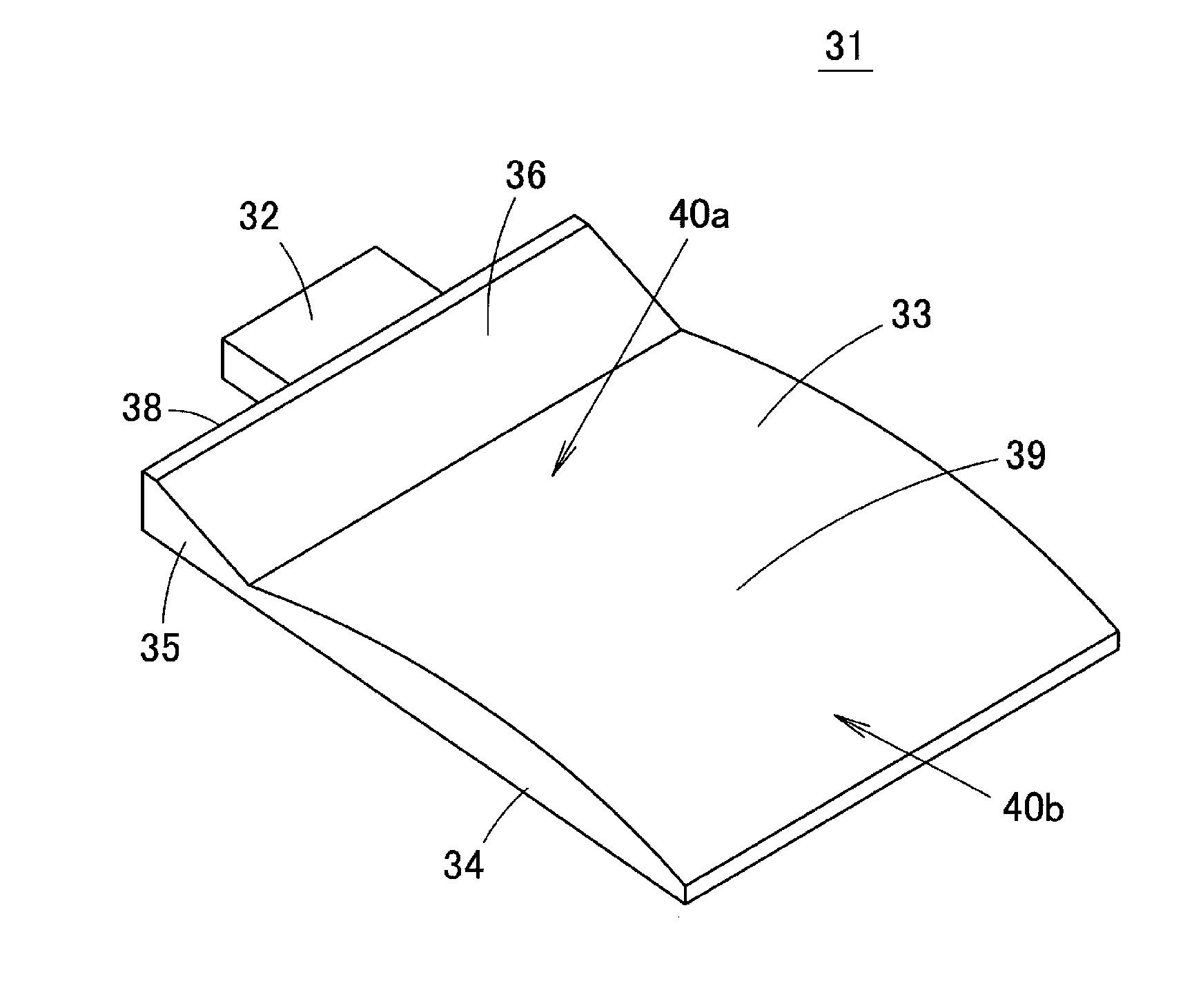
[0032]A surface light source device 31 according to a first embodiment of the present invention will be described below with reference to FIGS. 3 to 5. FIG. 3 is a perspective view illustrating the surface light source device 31 of the present invention. FIG. 4 is a schematic side view illustrating the surface light source device 31. FIG. 5 is a view illustrating a behavior of light in the surface light source device 31.

[0033]The surface light source device 31 includes a point light source 32 (light source) and a light guide plate 33 configured to introduce light emitted from the light source 32 through a light incident surface to output the light through a light exit surface. As illustrated in FIG. 5, the point light source 32 is provided with one or a plurality of LEDs 41. In the point light source 32, the LED 41 emits light to output white light from a light exit window (emission surface) of a front surface. The point light source 32 is smaller than a width of the light guide pla...

second embodiment

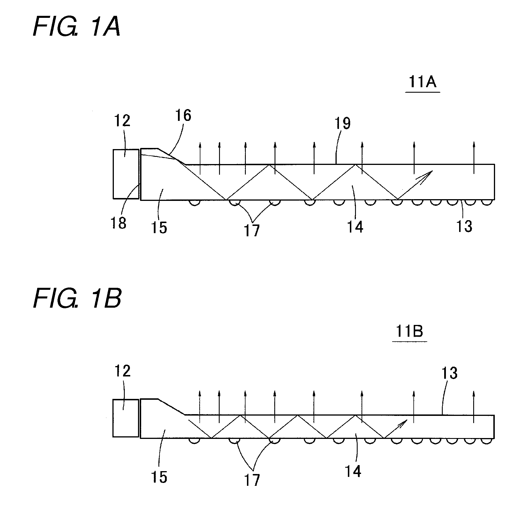
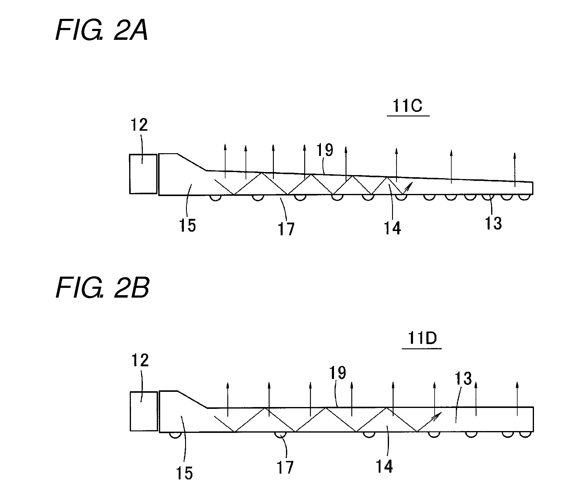
[0050]FIG. 7A is a schematic side view illustrating a surface light source device according to a second embodiment of the present invention. In the second embodiment, the upper surface of the light guide plate body 34 constitutes a flat surface. The lower surface of the light guide plate 33 is curved, and the light exit pattern 37 is provided in the lower surface of the light guide plate body 34.

[0051]The lower surface in the light-source side edge portion of the light guide plate body 34 constitutes a curved first gradient surface 42a. The first gradient surface 42a is inclined downward with increasing distance from the point light source 32, and the light-source side edge portion of the light guide plate body 34 is gradually increased in thickness with increasing distance from the point light source 32. When measured downward from the horizontal surface, the angle of inclination (a) of the first gradient surface 42a is gradually decreased with increasing distance from the point li...

third embodiment

[0054]FIG. 7B is a schematic side view illustrating a surface light source device according to a third embodiment of the present invention. In the light-source side edge portion of the light guide plate body 34, the first gradient surface 40a, which is inclined upward with increasing distance from the point light source 32 and curved so as to swell upward, is provided in the upper surface of the light guide plate body 34, and the first gradient surface 42a, which is inclined downward with increasing distance from the point light source 32 and curved so as to swell downward, is provided in the lower surface of the light guide plate body 34. As a result, the light-source side edge portion of the light guide plate body 34 is gradually increased in thickness with increasing distance from the point light source 32.

[0055]In the end portion located on the side farther away from the light source of the light guide plate body 34, the second gradient surface 40b, which is inclined downward wi...


PUM


Abstract

A surface light source device has a point light source disposed opposite a light incident surface of a light guide plate. The light guide plate includes a light introduction part, and a light guide plate body having a thickness smaller than a maximum thickness of the light introduction part. The light introduction part includes an inclined surface inclined from a surface in a portion having a thickness larger than the thickness of the light guide plate body toward an end of the surface of the light guide plate body. The light guide plate body has a light exit pattern for reflecting the light in the light guide plate body to output the light from a light exit surface. In a region close to the point light source of the light guide plate body, the thickness of the light guide plate body increases gradually with distance from the point light source.

Description

1. TECHNICAL FIELD[0001]The present invention relates to a surface light source device, and specifically to a surface light source device that is used as a backlight of a liquid crystal display.2. BACKGROUND ART[0002]Nowadays, there is an increasing demand for a low profile of a surface light source device with the progress of a low-profile mobile device provided with the surface light source device. In order to reduce a thickness of the surface light source device, it is necessary to reduce a thickness of a light guide plate. However, even if the flat light guide plate can be reduced in thickness, there is a limitation to reducing a height of a light source including an LED. Therefore, in the case where the thin, flat light guide plate is used, the height of the light source is larger than a thickness of an end surface (a light incident surface) of the light guide plate, and the light source disposed opposite to the light incident surface of the light guide plate projects above fro...

Claims


Application Information

Patent Timeline
IPC IPC(8): F21V8/00
CPCG02B6/0028G02B6/0018G02B6/0046G02B6/0036G02B6/002
Inventor KURATA, GOUOTAKEMURA, KOICHISHIBATA, TOMOFUSASHINOHARA, MASAYUKI
Owner ORMON CORP
Why Eureka
Try Eureka