Method and apparatus for protection switching in optical transport network
a technology of optical transport network and protection switch, applied in multiplex communication, optics, instruments, etc., can solve the problem that the bandwidth set for each oduflex cannot be effectively operated
- Summary
- Abstract
- Description
- Claims
- Application Information
AI Technical Summary
Benefits of technology
Problems solved by technology
Method used
Image

Examples
first embodiment
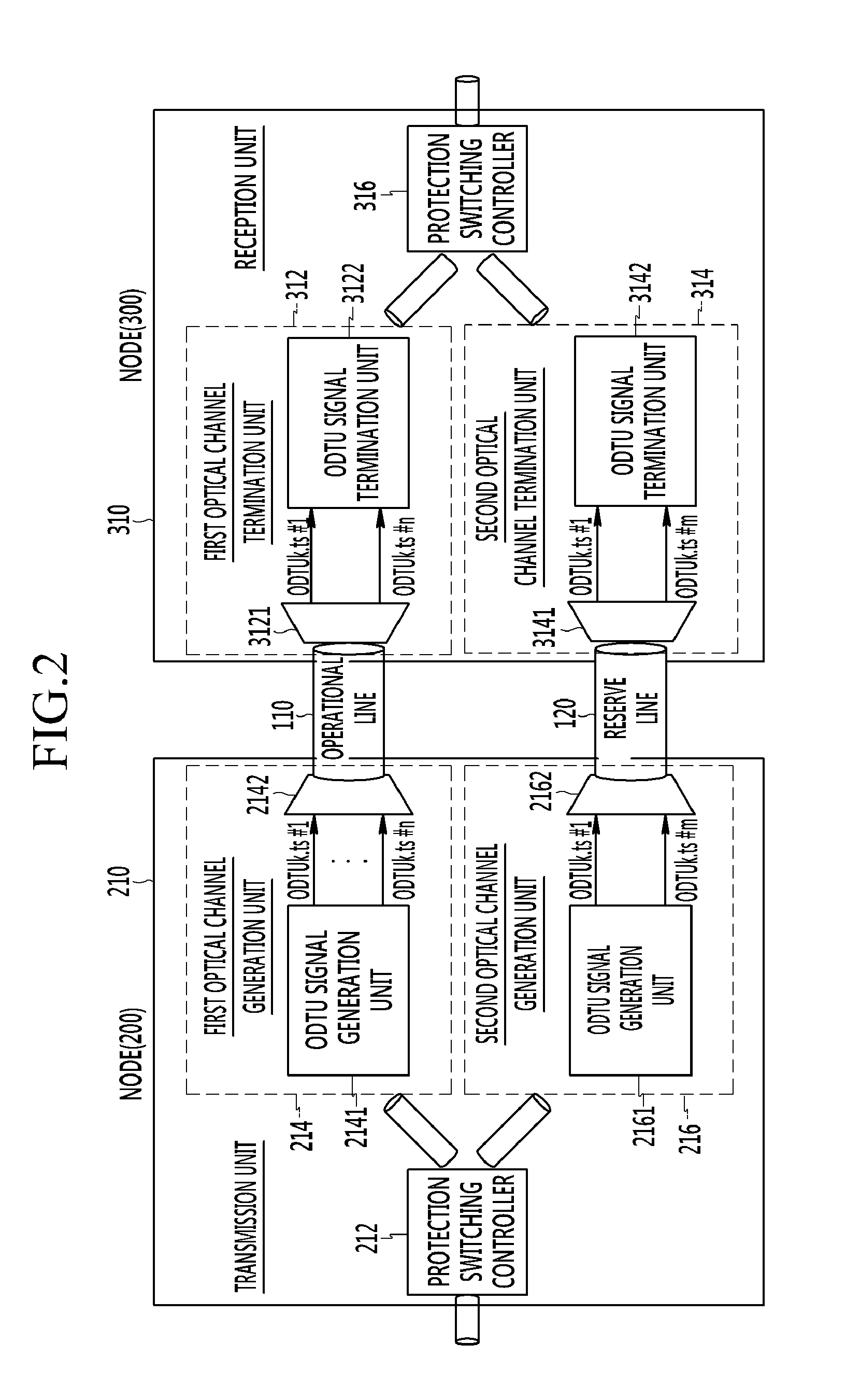
[0034]FIG. 2 is a view schematically showing nodes of an optical transport network system for unidirectional optical transmission according to the present invention.
[0035]With reference to FIG. 2, a node 200 of the optical transport network system is connected to a different node 300 through an optical transport network interface.
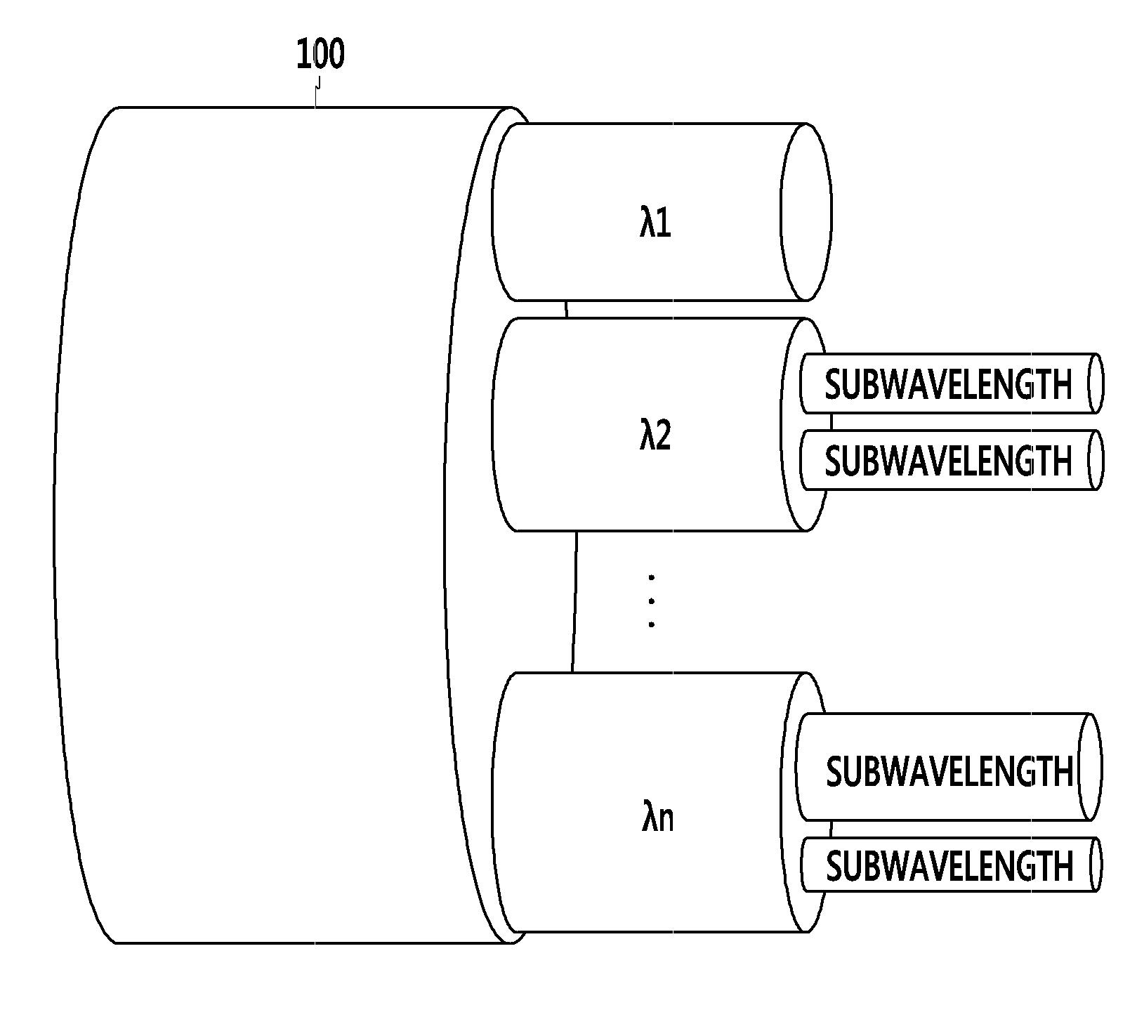
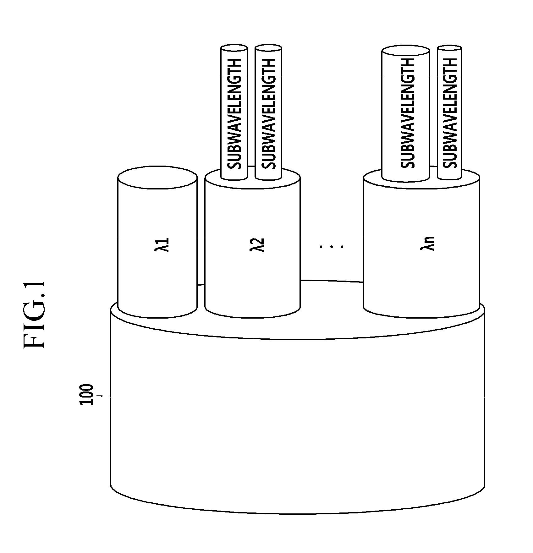
[0036]The optical transport network interface includes an operational line 110 and a reserve line 120. The operational line 110 and the reserve line 120 include a plurality of optical wavelengths, respectively, and each of the plurality of optical wavelengths includes a plurality of optical channels. Here, each optical channel corresponds to ODUflex. Thus, different bandwidths may be allocated to the respective optical channels.
[0037]The node 200 transmits a plurality of optical wavelengths to the node 300 via the operational line 110. When there is a fault in at least one of the optical channels of the operational line, the fault-generated optical channel ...
second embodiment
[0065]FIG. 5 is a flowchart illustrating a process of a method for protection switching in an optical transport network system for a uni-directional optical transmission according to the present invention.
[0066]In FIG. 5, it is illustrated that the operational line 110 is comprised of two optical wavelengths, the reserve line 120 is comprised of one optical wavelength, each of the optical wavelengths of the operational line 110 includes two optical channels, and the optical wavelength of the reserve line 120 includes three optical channels.
[0067]As shown in FIG. 5, the operational line 110 and the reserve line 120 may include at least one optical wavelength, and the number of the optical wavelengths of the reserve line 120 may be equal to or smaller than that of the optical wavelengths of the operational line 110. In order to enhance transmission efficiency of the optical transport network, the number of optical wavelengths of the reserve line 120 may be set to be smaller than that ...
third embodiment
[0073]FIG. 6 is a view schematically showing an optical transport network system for bi-directional optical transmission according to the present invention.
[0074]With reference to FIG. 6, the nodes 200 and 300 include transmission units 210 and 320 and reception units 220 and 310, respectively.
[0075]The reception unit 220 of the node 200 may be configured to be identical to the reception unit 310 of the node 300, and the transmission unit 320 of the node 300 may be configured to be identical to the transmission unit 210 of the node 200.
[0076]The transmission unit 210 of the node 200 and the reception unit 310 of the node 300 may be connected to one operational line and one reserve line, and the reception unit 220 of the node 200 and the transmission unit 320 of the node 300 may be connected to another operational line and another reserve line.
[0077]The method for protection switching performed between the reception unit 220 of the node 200 and the transmission unit 320 of the node 3...
PUM
 Abstract
Description
Claims
Application Information
 - Generate Ideas
- Intellectual Property
- Life Sciences
- Materials
- Tech Scout
- Unparalleled Data Quality
- Higher Quality Content
- 60% Fewer Hallucinations
Browse by: Latest US Patents, China's latest patents, Technical Efficacy Thesaurus, Application Domain, Technology Topic, Popular Technical Reports.
© 2025 PatSnap. All rights reserved.Legal|Privacy policy|Modern Slavery Act Transparency Statement|Sitemap|About US| Contact US: help@patsnap.com