Active antenna array with modulator-based pre-distortion

a modulator-based, active antenna technology, applied in the direction of polarisation/directional diversity, electromagnetic wave modulation, baseband system details, etc., can solve the problems of adding to the cost of predistortion modulation signal distribution structure, or of components thereof such as digital-to-digital, and achieve the effect of degree of flexibility

Active Publication Date: 2013-01-08
TELEFON AB LM ERICSSON (PUBL)
View PDF15 Cites 17 Cited by
  • Summary
  • Abstract
  • Description
  • Claims
  • Application Information

AI Technical Summary

Benefits of technology

[0011]The predistortion modulation signal distribution structure should be suitable for distributing the predistortion modulation signal in a substantially unaltered manner To this end, the predistortion modulation signal distribution structure may need to meet certain specifications with respect to, for example bandwidth and dynamic range. This might add to the costs of the predistortion modulation signal distribution structure, or of components thereof such as digital-to-analogue converters. On the other hand, the transmission path signals feeding the transmit paths are now much narrower in bandwidth than they would be if baseband digital predistortion was also included in the signal spectra. There is usually a number of transmission paths in an active antenna array so that the higher costs for the predistortion modulation signal distribution structure are usually more than compensated by the savings effected by the option of using smaller bandwidth equipment in the transmission paths. For a single transmission path or in a conventional active antenna array, this advantage is diluted by the fact that the predistortion modulation signal generator and the predistortion modulation signal distribution structure is required once per transmission path, to supply the predistortion modulation signal(s) to the vector modulator(s). The teachings disclosed herein, however, are based on the insight that the signal being processed in at least two of the plurality of transmission paths are substantially identical (from a modulation perspective), with only RF carrier phase differences and / or absolute amplitude level differences (but not differences in the shape of the envelope) between the channels (to form / steer a beam radiated by an antenna array connected to the active antenna array or a part of the active antenna array). It is also recognized that power amplifiers in the plurality of transmission paths are nearly identical, having been fabricated from the same size / type of device or making use of integrated circuit power amplifiers of identical design and fabrication. The non-linearity characteristics of these power amplifiers are likely to be very similar and hence the same correction signals can be used for all of them. This reduces the number of components that are needed for implementing the predistortion modulation signal generator and the predistortion modulation distribution structure.
[0030]The at least two of the plurality of transmission paths may comprise a delta-sigma modulator adapted to frequency converter the at least two transmission path signals. The teachings disclosed herein make the utilization of delta-sigma modulators possible for applications that require good linearity of the transmission paths and thus the application of some sort of predistortion. As mentioned above, many predistortion schemes require the transmission paths to have a large bandwidth that is much larger than the bandwidth of a payload signal alone. Delta-sigma modulators, although otherwise well suited for the applications at hand, would not qualify due to their usually limited bandwidth. The teachings disclosed herein make the utilization of such delta-sigma modulators possible in these cases, since the transmission paths are not concerned with carrying high-bandwidth predistortion signal components.

Problems solved by technology

This might add to the costs of the predistortion modulation signal distribution structure, or of components thereof such as digital-to-analogue converters.

Method used


Image

  • Active antenna array with modulator-based pre-distortion
  • Active antenna array with modulator-based pre-distortion
  • Active antenna array with modulator-based pre-distortion

Examples


Embodiment Construction

[0054]The invention will now be described on the basis of the drawings. It will be understood that the embodiments and aspects of the invention described herein are only examples and do not limit the protective scope of the claims in any way. The invention is defined by the claims and their equivalents. It will be understood that features of one aspect can be combined with a feature of a different aspect or aspects.

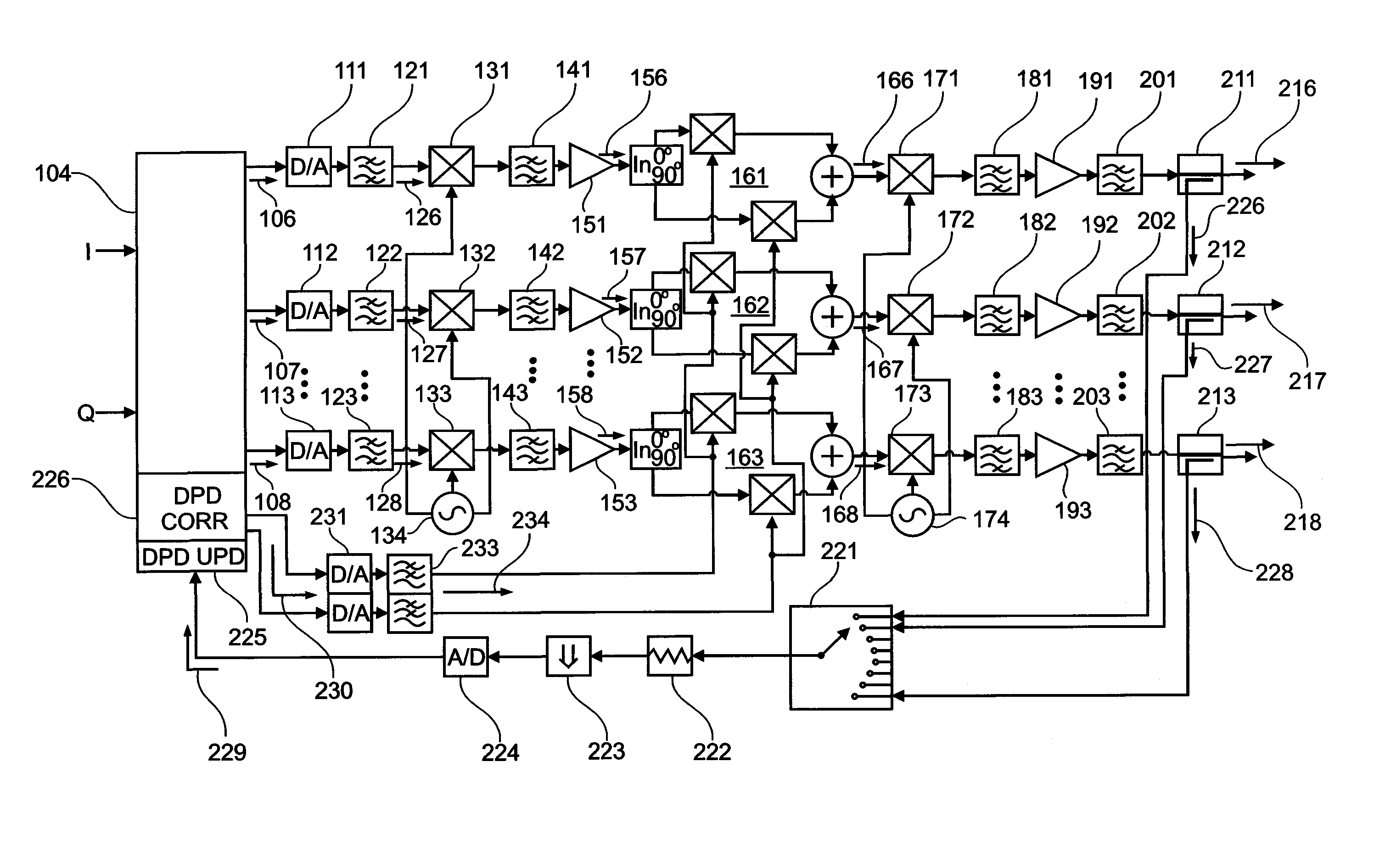
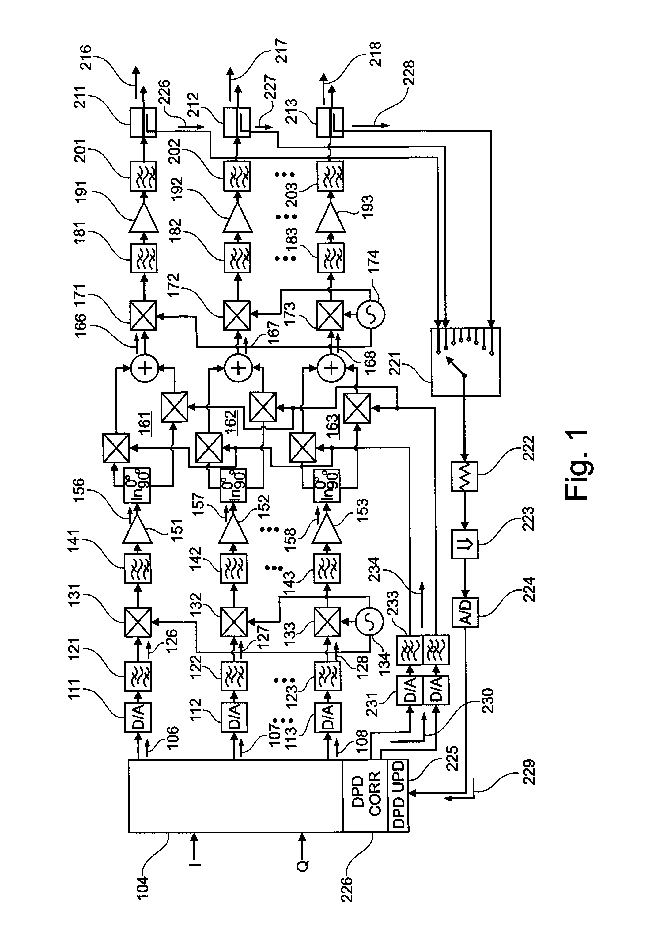
[0055]FIG. 1 shows a schematic block diagram of an active antenna array comprising a plurality of transmission paths. Only a first transmission path at the top, a second transmission path in the middle and a last or n'th transmission path at the bottom are illustrated in FIG. 1, as well as in the similar subsequent figures. The third, to the (n−1)'th, transmission paths are not illustrated for the sake of clarity.

[0056]A signal to be transmitted reaches the active antenna array from the left. In FIG. 1 the signal to be transmitted is illustrated as comprising an in-phase ...


PUM


Abstract

An active antenna array comprises a plurality of transmission paths, a predistortion modulation signal generator, and a predistortion modulation signal distribution structure. At least two of the plurality of transmission paths comprise a predistortion modulator for modulating a transmission path signal with a predistortion modulation signal generated by the predistortion modulation signal generator and distributed by predistortion modulation signal distribution structure to the at least two of the plurality of transmission paths. A method for predistorting at least two of a plurality of transmission path signals in an active antenna array and computer program products for manufacture and method execution are also claimed.

Description

FIELD OF THE INVENTION[0001]The field of the present invention relates to transmitter linearisation in an active antenna array. The field of the present invention further relates to a method for predistorting transmission path signals in an active antenna array.BACKGROUND OF THE INVENTION[0002]Modern communication standards sometimes require linear power amplification in contrast to, for example, frequency-modulation (FM) based systems for which highly non-linear transmitters and receivers were sufficient. Modern mobile communications standards such as UMTS, WiMAX and Long Term Evolution (LTE) are also intended to support a variety of different channel coding and modulation techniques (CDMA, OFDM, etc.), broader channel bandwidths and high peak-to-average power ratio (PAPR) modulation schemes. Moreover, there is an increasing demand for base stations supporting a wider range of frequency bands. Such base stations are more flexible and may be reconfigured if new frequency slots becom...

Claims


Application Information

Patent Timeline
Patent Type & Authority Patents(United States)
IPC IPC(8): H04L25/03
CPCH03F1/3247H03F3/195H03F3/24H03F3/68H04B1/0483H03F2200/336
Inventor KENINGTON, PETER
Owner TELEFON AB LM ERICSSON (PUBL)
Why Eureka
Try Eureka