

Image forming apparatus
a technology of forming apparatus and forming tube, which is applied in the direction of electrographic process apparatus, instruments, optics, etc., to achieve the effect of suppressing the thermochromism phenomenon, high accuracy of color matching and color stability
- Summary
- Abstract
- Description
- Claims
- Application Information
AI Technical Summary
Benefits of technology
Problems solved by technology
Method used
Image

Examples
embodiment 1
Image Forming Apparatus
[0047]In the present embodiment, a method for solving the foregoing problem will be described using an electrophotographic laser beam printer. Here, the electrophotographic system is employed as an example of the image forming system. Meanwhile, the present invention can also be applied to the inkjet printer and the sublimation printer. This is because the present invention is effective in image forming apparatuses where a thermochromism phenomenon is possibly caused in which chromaticity of a measurement target object changes due to temperature. Note that in the inkjet printer, an image forming unit for by discharging ink to form an image on a printing medium and a fixing unit (drying unit) for drying the ink are used.
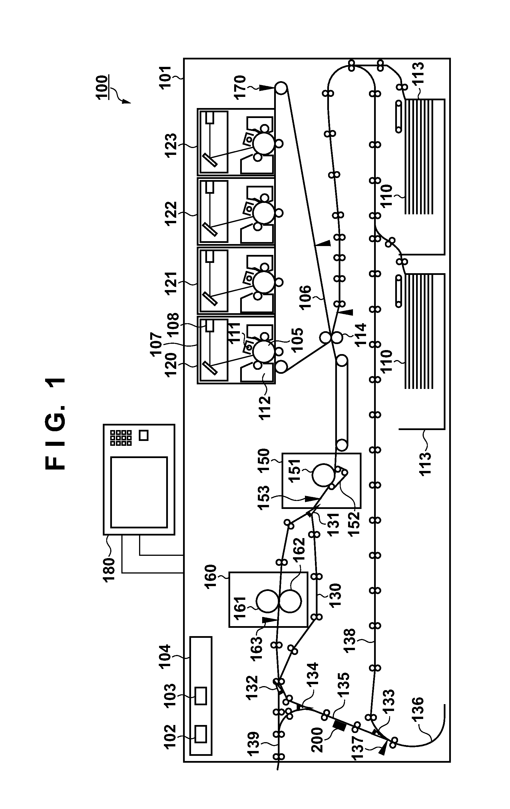
[0048]FIG. 1 is a cross-sectional diagram showing a configuration of an image forming apparatus 100. The image forming apparatus 100 has a housing 101. The housing 101 is provided with mechanisms for constituting an engine portion, and a control...
embodiment 2
[0095]The feature of the present embodiment lies in that the colorimetric value measurement is performed by the color sensor 200 after the prescribed time period T without using the timer 310 in the engine control portion 102 in the image forming apparatus 100. Specifically, the present embodiment would be effective in image forming apparatuses that have no waiting position where the printing medium 110 is caused to wait.
Image Forming Apparatus
[0096]The configuration of the image forming apparatus according to the present embodiment will be hereinafter described. FIG. 11A shows an example in which a buffer portion 141 is provided inside the image forming apparatus 100, and FIG. 11B shows an example in which the buffer portion 141 is provided outside the image forming apparatus 100.
[0097]In FIG. 11A, the buffer portion 141 is arranged on the downstream side of the inversion portion 136 in the conveyance direction of the printing medium 110. The engine control portion 102 switches bet...
third embodiment
Maximum Density Adjustment
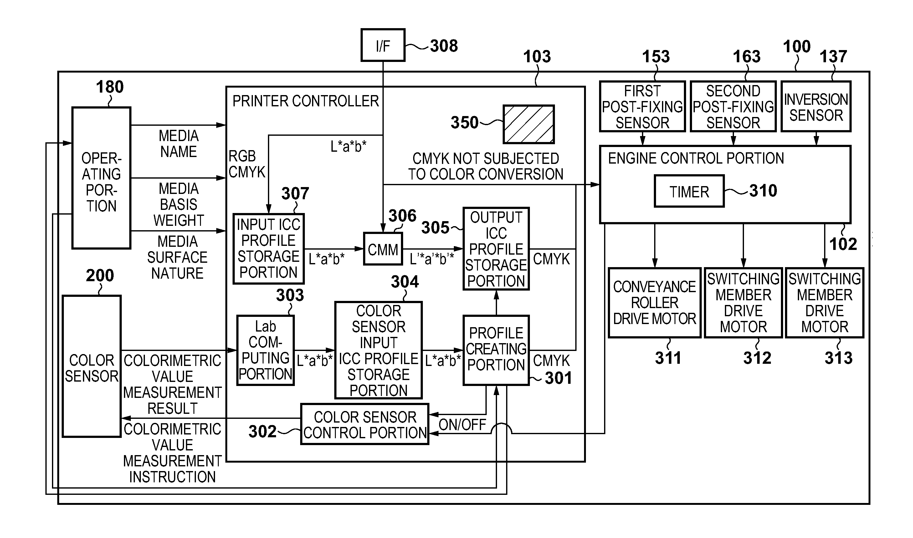
[0110]FIG. 14 is a block diagram showing the system configuration of the image forming apparatus 100. Initially, the printer controller 103 instructs the engine control portion 102 to output a test chart used in maximum density adjustment. At this time period, a patch image for the maximum density adjustment for YMCK colors is formed on the printing medium 110 with the charging potential, exposure intensity, and developing bias that are set in advance, or set for the last maximum density adjustment. After that, the engine control portion 102 instructs the color sensor control portion 302 to measure a colorimetric value of the patch image.
[0111]After the colorimetric value of the patch image is measured by the color sensor 200, the colorimetric value measurement result is transmitted as spectral reflectance data to a density converting portion 324. The density converting portion 324 converts the spectral reflectance data into density data on CMYK, and transm...
PUM
 Abstract
Description
Claims
Application Information