
Liquid circulating device and medical apparatus

a technology of liquid circulating device and medical device, which is applied in the direction of pump control, positive displacement liquid engine, pump, etc., can solve the problems of small channel section area and decrease of liquid circulation efficiency, and achieve the effect of ensuring stability of circulation efficiency

Inactive Publication Date: 2013-09-19
SEIKO EPSON CORP
View PDF4 Cites 6 Cited by
  • Summary
  • Abstract
  • Description
  • Claims
  • Application Information

AI Technical Summary

Benefits of technology

This patent is about a liquid circulating device that ensures stability of circulation efficiency. The device regulates pressure to prevent the pressure inside the circulation channel from dropping significantly during the operation of the volume changing unit. This helps to secure stable circulation efficiency. The device can also be used in a liquid ejecting apparatus to ensure consistent liquid flow.

Problems solved by technology

However, since the liquid circulating device of the related art is not configured in consideration of the pressure inside the circulation channel during the operation, problems that occur, depending on operating conditions, are for example, the cross-sectional area of the channel becomes small, and a decrease of circulation efficiency of the liquid have been pointed out.

Method used


Image

  • Liquid circulating device and medical apparatus
  • Liquid circulating device and medical apparatus
  • Liquid circulating device and medical apparatus

Examples


first example

A. First Example

A1. System Configuration:

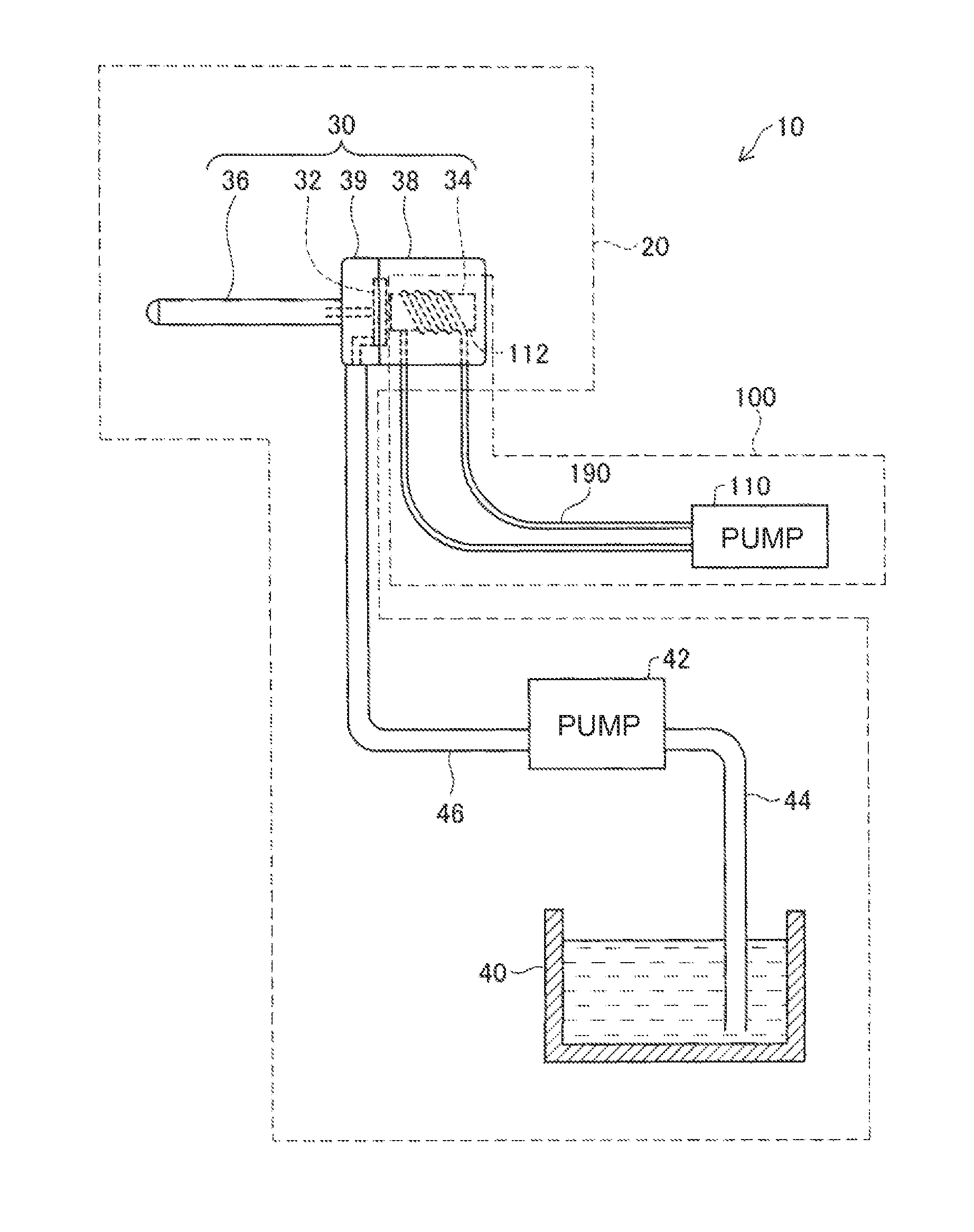
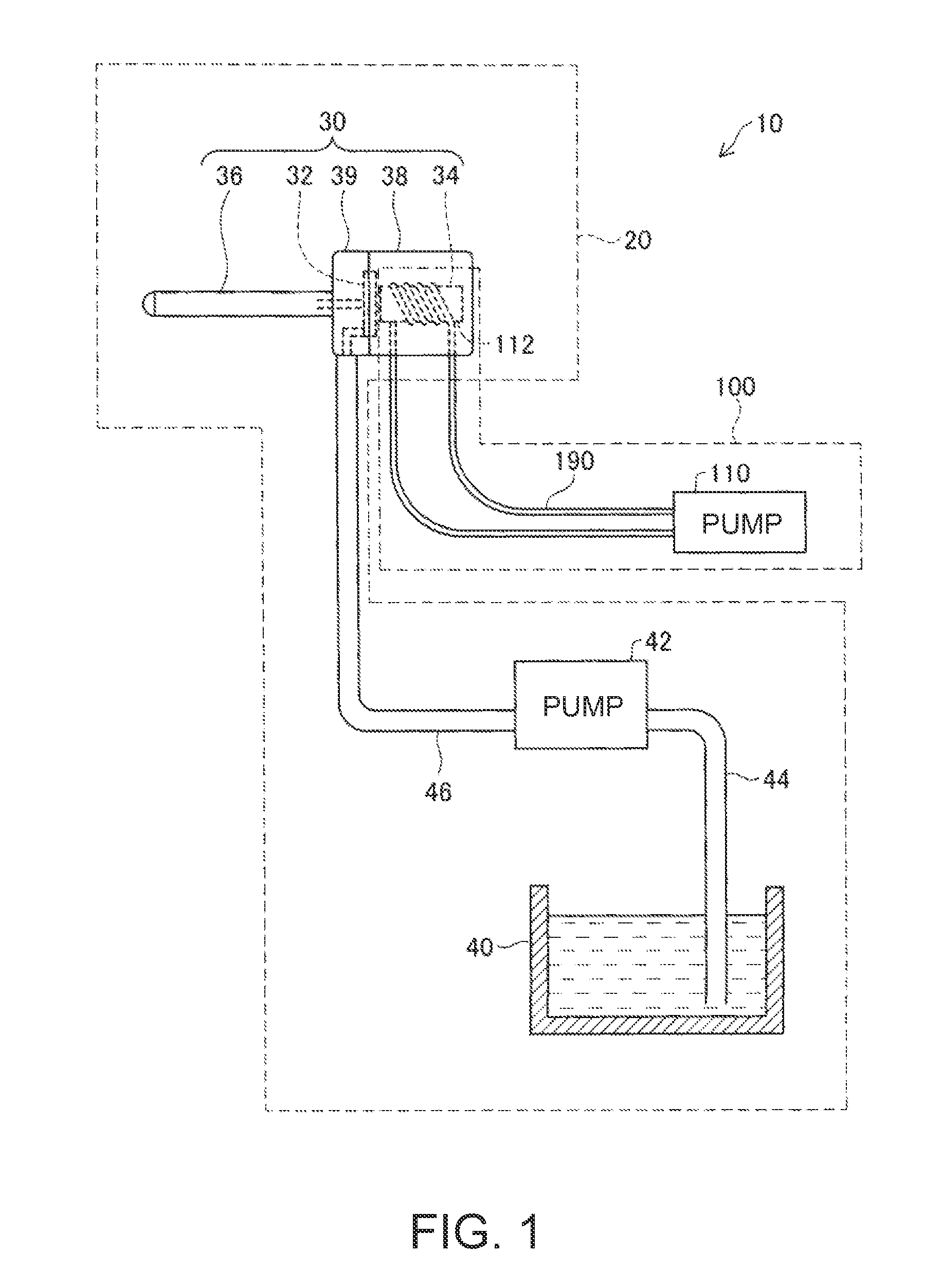
[0038]Embodiments of the invention will be described on the basis of examples. FIG. 1 is an explanatory view showing the schematic configuration of a liquid ejecting system 10 as one example of the invention. The liquid ejecting system 10 is equipped with a liquid ejecting apparatus 20 and a liquid circulating device 100 that cools the liquid ejecting apparatus 20. The liquid ejecting apparatus 20 is a water jet knife that ejects a jet water stream to living body tissues, such as the skin. Particularly, the liquid ejecting apparatus 20 of the present example is a water jet pulse scalpel that exfoliates and incises living body tissues.

[0039]The liquid ejecting apparatus 20 is equipped with a pulsation generator 30 that ejects a jet water stream, a liquid container 40 that contains water, a supply pump 42 that pumps the water contained in the liquid container 40 to supply the water to the pulsation generator 30, a connecting tube 44 that connec...

second example

B. Second Example

[0078]Next, a second example of the invention will be described. In a second example, as the liquid circulating device, a liquid circulating device 200 is used instead of the liquid circulating device 100. In the liquid circulating device 100 in the first example, the pressure regulation liquid BF is contained in the film pack 160. However, in the liquid circulating device 200 in the second example, instead of the film pack 160, the pressure regulation liquid BF is contained in a branch channel 210 provided in the liquid channel 190. Since components other than the branch channel 210 are the same as those of the first example, description of the components other than the branch channel 210 is omitted. In addition, the same reference numerals are given to the same components in the first example and the second example.

[0079]FIG. 6 is an explanatory view illustrating the configuration of the branch channel 210 in the present example. The branch channel 210 is provided...

modification examples

C. Modification Examples

[0088]The invention is not limited to the above examples or embodiments, and can be carried out in various aspects without departing from the scope of the invention. For example, the following modifications can also be made.


PUM


Abstract

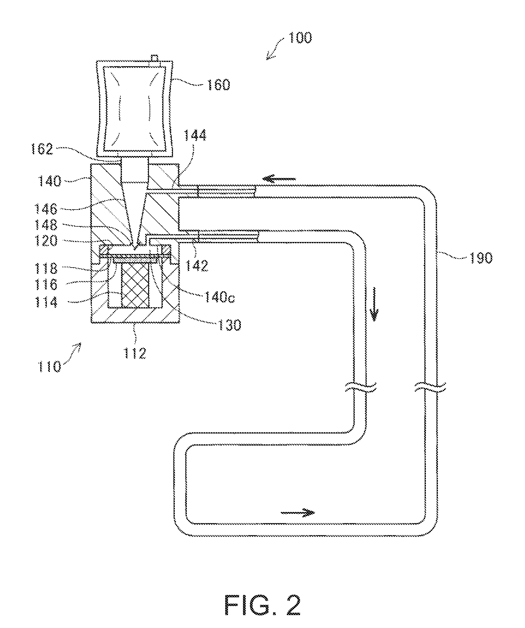
A liquid circulating device includes a pump chamber whose volume is changed by a volume changing unit; an inlet channel that is an inflow passage of the liquid to the pump chamber; a liquid resistance element; an outlet channel; a circulation channel of a length L through which the liquid circulates from the outlet channel to the inlet channel; and a pressure regulating mechanism that contains the liquid of a volume Vb during the non-operation of the volume changing unit and supplies the contained liquid as part of the circulating liquid during the operation of the volume changing unit. When the compliance of the circulation channel is defined as Cs, and the pressure of the liquid in the circulation channel at the position of a length x from the outlet channel during the operation of the volume changing unit is defined as P(x), the volume Vb satisfies a predetermined relationship.

Description

BACKGROUND[0001]1. Technical Field[0002]The present invention relates to a liquid circulating device.[0003]2. Related Art[0004]In the related art, a technique using a liquid circulating device is known as the technique for adjusting the temperature of an object (for example, JP-A-8-242463). This technique brings a circulation channel, through which a liquid circulates, into contact with a target (hereinafter referred to as a temperature adjustment target) whose temperature is intended to be adjusted, and adjusts the temperature of the temperature adjustment target depending on the temperature of the liquid that is circulated. However, since the liquid circulating device of the related art is not configured in consideration of the pressure inside the circulation channel during the operation, problems that occur, depending on operating conditions, are for example, the cross-sectional area of the channel becomes small, and a decrease of circulation efficiency of the liquid have been po...

Claims


Application Information

Patent Timeline
Patent Type & Authority Applications(United States)
IPC IPC(8): F04B23/00
CPCF04B43/095A61B17/3203F04B23/00
Inventor SETO, TAKESHIOSHIMA, ATSUSHIMATSUZAKI, TAKAHIROUCHIDA, KAZUAKIHIRABAYASHI, ATSUYA
Owner SEIKO EPSON CORP
Learn More