Exhaust gas control apparatus and control method for exhaust gas control apparatus

a control apparatus and control method technology, applied in mechanical apparatus, engine components, machines/engines, etc., can solve the problems of ammonia slippage, ammonia purification rate, and ammonia slipping, so as to improve the purification rate of exhaust gas and the effect of improving the purification ra

Active Publication Date: 2013-09-26
TOYOTA JIDOSHA KK +2
View PDF4 Cites 14 Cited by
  • Summary
  • Abstract
  • Description
  • Claims
  • Application Information

AI Technical Summary

Benefits of technology

[0013]The invention has been designed in consideration of the points described above, and provides a technique employed in an exhaust gas control apparatus having a NOx reduction catalyst that is provided in an exhaust system of an internal combustion engine in order to reduce and remove NOx contained in exhaust gas using ammonia supplied and adsorbed thereto from an upstream side in an exhaust gas flow direction, with which a NOx purification rate can be improved and ammonia slip can be suppressed.
[0014]More generally, the invention provides a technique employed in an exhaust gas control apparatus having an exhaust gas control member that is provided in an exhaust system of an internal combustion engine in order to control exhaust gas using a purifying agent supplied and adsorbed thereto from an upstream side in an exhaust gas flow direction, with which an exhaust gas purification rate can be improved and outflow of the purifying agent from the exhaust gas control member can be suppressed.

Problems solved by technology

There is, however, an upper limit to the amount of ammonia that can be adsorbed to the NOx reduction catalyst, and when an excessive amount of ammonia exceeding the upper limit is supplied to the NOx reduction catalyst, ammonia slip, whereby the ammonia that cannot be adsorbed to the NOx reduction catalyst flows out of the NOx reduction catalyst, becomes more likely to occur.
Hence, in an exhaust gas control apparatus having a NOx reduction catalyst, it is difficult to realize an improvement in the NOx purification rate while suppressing ammonia slip.
It may therefore be impossible to realize sufficiently an effect of improving the NOx purification rate while suppressing ammonia slip.

Method used


Image

  • Exhaust gas control apparatus and control method for exhaust gas control apparatus
  • Exhaust gas control apparatus and control method for exhaust gas control apparatus
  • Exhaust gas control apparatus and control method for exhaust gas control apparatus

Examples


first embodiment

[0132]First, an example of urea addition control according to the invention, in which the ammonia adsorption amount in a predetermined region of the NOx reduction catalyst 7 is determined from the ammonia adsorption amount distribution through the NOx reduction catalyst 7 and the urea addition control is performed on the basis thereof, will be described.

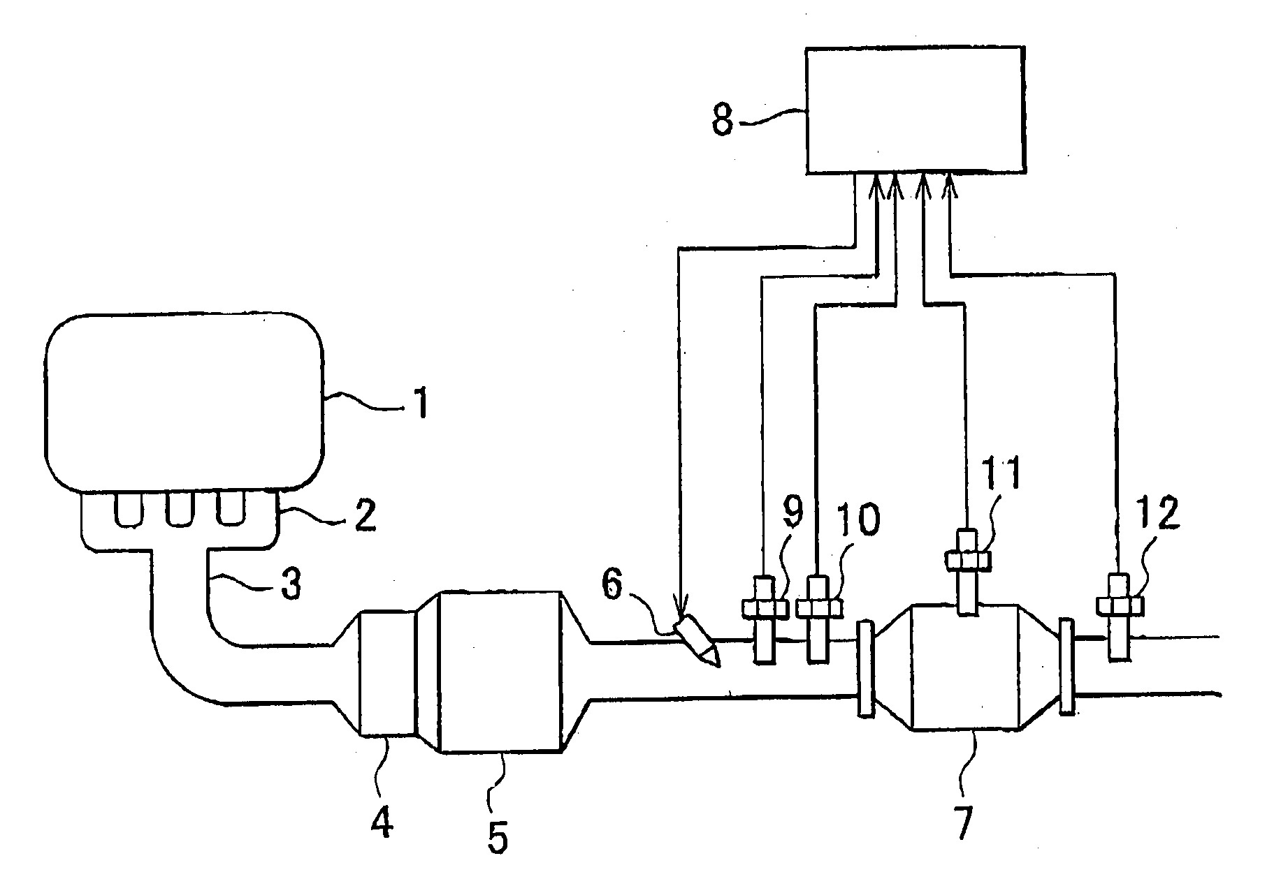
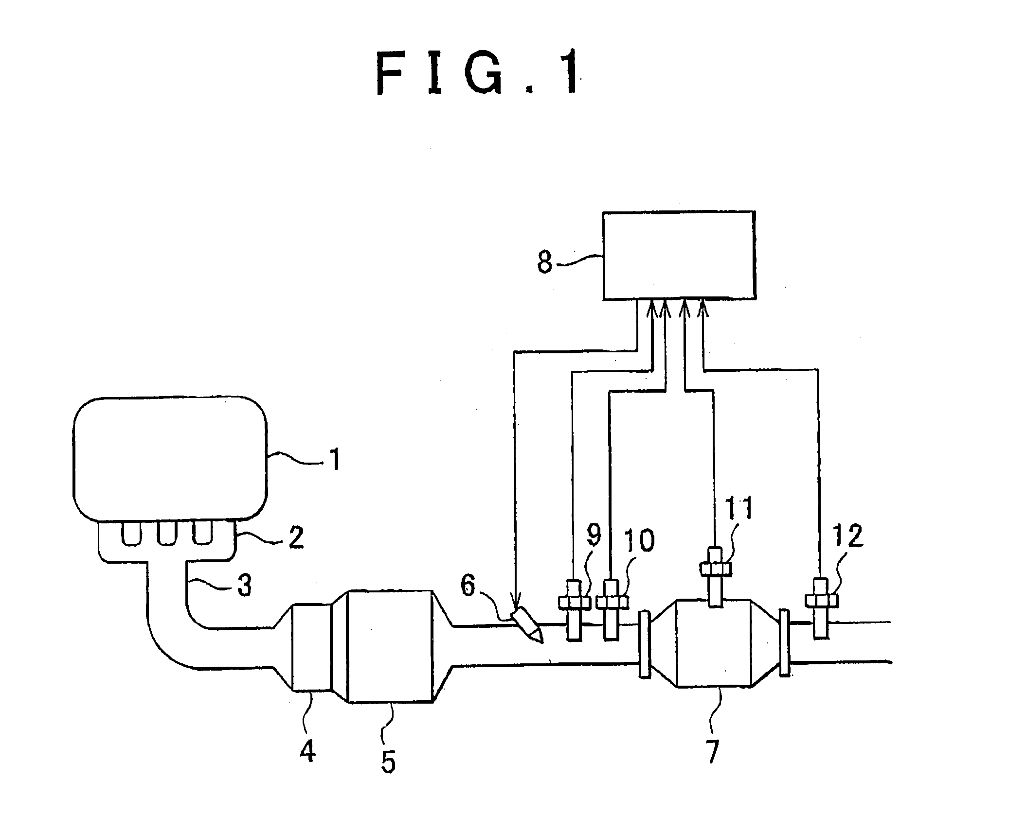
[0133]In the first embodiment, as shown in FIG. 4, the ammonia adsorption amount distribution through the NOx reduction catalyst 7 is obtained using a model in which the NOx reduction catalyst 7 is divided into two cells. Hereafter, an upstream side part 71 in the exhaust gas flow direction will be referred to as a first cell, and a downstream side part 72 in the exhaust gas flow direction will be referred to as a second cell. In the first embodiment, urea addition control is performed on the basis of the ammonia adsorption amount in the second cell 72.

[0134]When ammonia adsorbed to the first cell 71 desorbs from the NOx reduction ca...

second embodiment

[0166]Next, an example of urea addition control according to the invention, in which a likelihood of ammonia slip is determined from the ammonia adsorption amount distribution through the NOx reduction catalyst 7 and the urea addition control is performed on the basis thereof, will be described.

[0167]FIGS. 7A and 7B are views illustrating a method of determining the likelihood of ammonia slip. FIG. 7A is a view showing the ammonia adsorption amount distribution through the NOx reduction catalyst 7. The abscissa in FIG. 7A shows an exhaust gas flow direction position (coordinate) within the NOx reduction catalyst 7, and the ordinate shows the ammonia adsorption amount. In FIG. 7A, a curve a (x) represents the ammonia adsorption amount distribution through the NOx reduction catalyst 7.

[0168]The adsorption amount distribution a (x) shown in FIG. 7A is an example of a distribution in which the ammonia adsorption amount in the vicinity of an inlet into the NOx reduction catalyst 7 is lar...

third embodiment

[0198]Hence, in the third embodiment, when a rapid increase in the temperature of the NOx reduction catalyst 7 is predicted on the basis of variation in the temperature of the exhaust gas flowing into the NOx reduction catalyst 7 or variation in the operating conditions of the internal combustion engine 1, urea addition is stopped or reduced in advance, even though an actual temperature increase has not yet occurred in the NOx reduction catalyst 7.

[0199]In the third embodiment, when a transitory state during which the operating conditions of the internal combustion engine 1 vary from a low load to a high load is detected, and when an increase in the temperature of the exhaust gas flowing into the NOx reduction catalyst 7 is detected by the exhaust gas temperature sensor 9, the slip determination values 1, 2 are corrected in accordance with the amount of variation in the load and the increase in the temperature of the exhaust gas. The slip determination values 1, 2 are corrected to s...


PUM


Abstract

An exhaust gas control apparatus includes a control device controlling a urea addition valve for adding urea from an upstream side of a NOx reduction catalyst. The control device obtains an ammonia adsorption amount distribution through the NOx reduction catalyst. When an ammonia adsorption amount in a predetermined part on a downstream side equals or exceeds a predetermined threshold, the control device controls the urea addition valve to stop the urea supply or reduce the amount thereof. The urea addition valve is controlled based on an adsorption amount distribution obtained from a model on which the catalyst is divided into cells such that an ammonia adsorption amount in a first cell positioned furthest upstream equals or exceeds a predetermined threshold close to a saturation adsorption amount and an ammonia adsorption amount in a second cell positioned downstream of the first cell reaches a predetermined target value smaller than the threshold.

Description

BACKGROUND OF THE INVENTION[0001]1. Field of the Invention[0002]The invention relates to an exhaust gas control apparatus and a control method for an exhaust gas control apparatus.[0003]2. Description of Related Art[0004]A nitrogen oxide (NOx) reduction catalyst that reduces NOx contained in exhaust gas from an internal combustion engine using ammonia as a reducing agent is employed as an exhaust gas control member. In an exhaust gas control apparatus having a NOx reduction catalyst, ammonia is supplied to the NOx reduction catalyst from an upstream side of the NOx reduction catalyst. A method of injecting urea water into the exhaust gas is generally employed as an ammonia supply method.[0005]The urea water injected into the exhaust gas decomposes in the exhaust gas so as to generate ammonia. The ammonia generated from the urea water is adsorbed to the NOx reduction catalyst. A redox reaction is promoted between the ammonia adsorbed to the NOx reduction catalyst and the NOx in the e...

Claims


Application Information

Patent Timeline
Patent Type & Authority Applications(United States)
IPC IPC(8): F01N3/08
CPCF01N3/208F01N2560/026F01N2560/06F01N2610/02F01N2610/146Y02T10/24F01N2900/1402F01N2900/1602F01N2900/1616F01N2900/1622F01N3/08F01N2900/0406Y02T10/12
Inventor HIROTA, SHINYATOSHIOKA, SHUNSUKEMIKAMI, AKIRAFUKUDA, KOICHIROHOSHI, SAKUTAROENDO, TAKASHIHIBINO, RYOICHIUEDA, MATSUEIASANO, AKIHIKOYAMAUCHI, TAKAFUMISHICHI, AKIRAKOIKE, MAKOTOMARUYAMA, MASATOSHISAKATA, MASAKAZU
Owner TOYOTA JIDOSHA KK
Why Eureka
Try Eureka