
Method and apparatus for protecting an optical detection device from contamination

a technology of optical detection and protection equipment, applied in the field of optical detection devices, can solve the problems of reducing the operating cost of the device, limiting the risk of unnecessary air turbulence, and attendant airborne contamination, and affecting the operation of the device. the effect of reducing the risk of air turbulen

Active Publication Date: 2013-09-26
DELAVAL HLDG AB
View PDF5 Cites 6 Cited by
  • Summary
  • Abstract
  • Description
  • Claims
  • Application Information

AI Technical Summary

Benefits of technology

The patent describes a device that prevents contamination of a window in a milking stall by creating an air curtain to protect it during other operations. The air curtain is generated when the other operation is initiated to ensure that the window is protected only when there is a risk of contamination. This not only reduces the operating cost of the device but also reduces the risk of unnecessary air turbulence and damage to the detector. Additionally, the device has a feature that allows it to position the detector close to an animal for better detection, but keep the air curtain in place to prevent contamination until the detector is moved away from the animal. Additionally, when the device is used for cleaning or treatment of the animal, the air curtain also helps prevent contamination of the detector. The device also has an air flow system that prevents dust or droplets from getting into the air curtain and obscuring the detector's field.

Problems solved by technology

This not only reduces the operating cost of the device, but it also limits the risk of unnecessary air turbulence close to the stall floor and thus also the attendant airborne contamination that could damage both the detector and other equipment in the milking stall.
When the detector is moved close to the teats of an animal, for example, in order to detect the teats and determine their position prior to cleaning or milking, there is a risk that milk droplets may land on the detector window, as in some animals, milk let-down is triggered simply by the act of entering the milk box and in most cases will have started when the teats have been washed.
In addition when the detector is located under an animal, there is a higher risk of dust or mud falling from the animal onto the detector window.

Method used


Image

  • Method and apparatus for protecting an optical detection device from contamination
  • Method and apparatus for protecting an optical detection device from contamination
  • Method and apparatus for protecting an optical detection device from contamination

Examples


Embodiment Construction

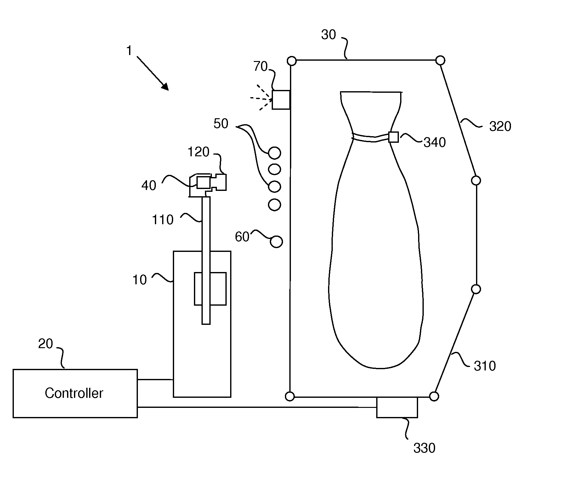
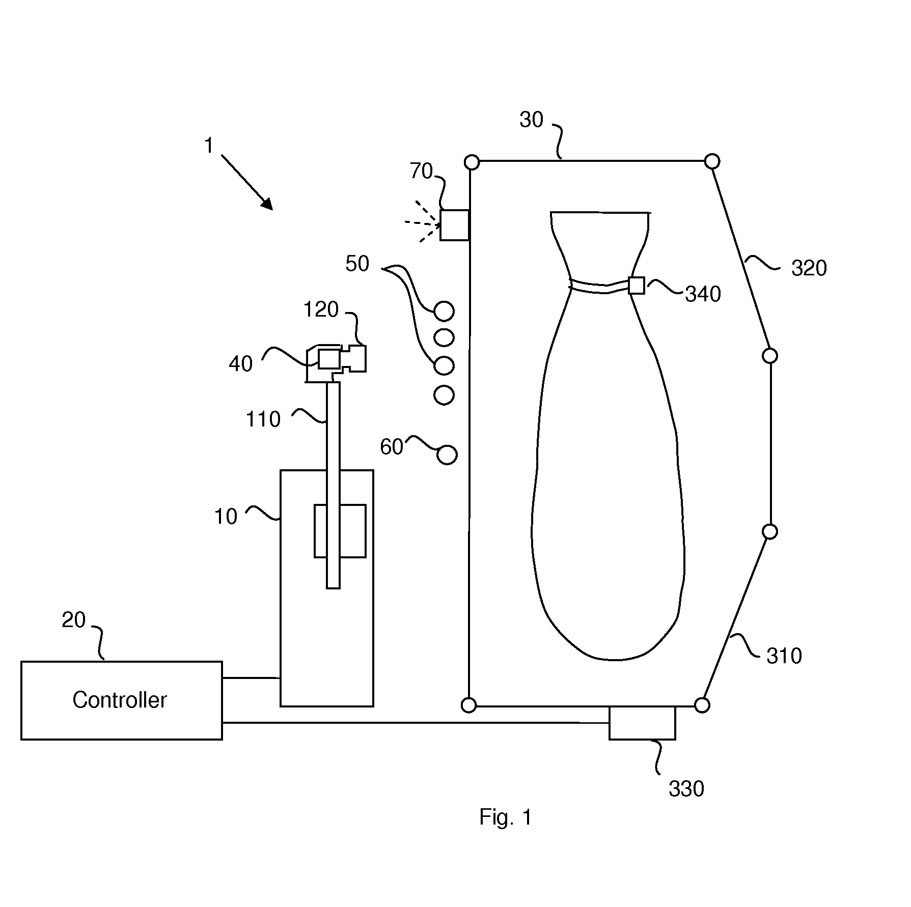
[0028]FIG. 1 shows an automatic milking system, which includes a milk box 30 for retaining an animal to be milked and a milking robot 1 disposed to one side of the milk box 30. The milk box 30 includes an entrance gate 310 and an exit gate 320. An identification device 330 is mounted on or near to the milk box 30 close to the entrance gate 310. This device 330 detects the unique identification of an animal standing before the milk box by detecting or interrogating a transponder 340, that is carried by the animal, for example on a collar, and holds a unique identification number or code assigned to the animal. The control of these gates will be described in more detail below. The milking robot 1 includes a robot arm construction 10 as well as a number of other components not shown in the figure but conventionally present in this type of arrangement. These components typically include, but are not limited to, milk and pulsation lines and associated elements of the milk and vacuum circ...


PUM


Abstract

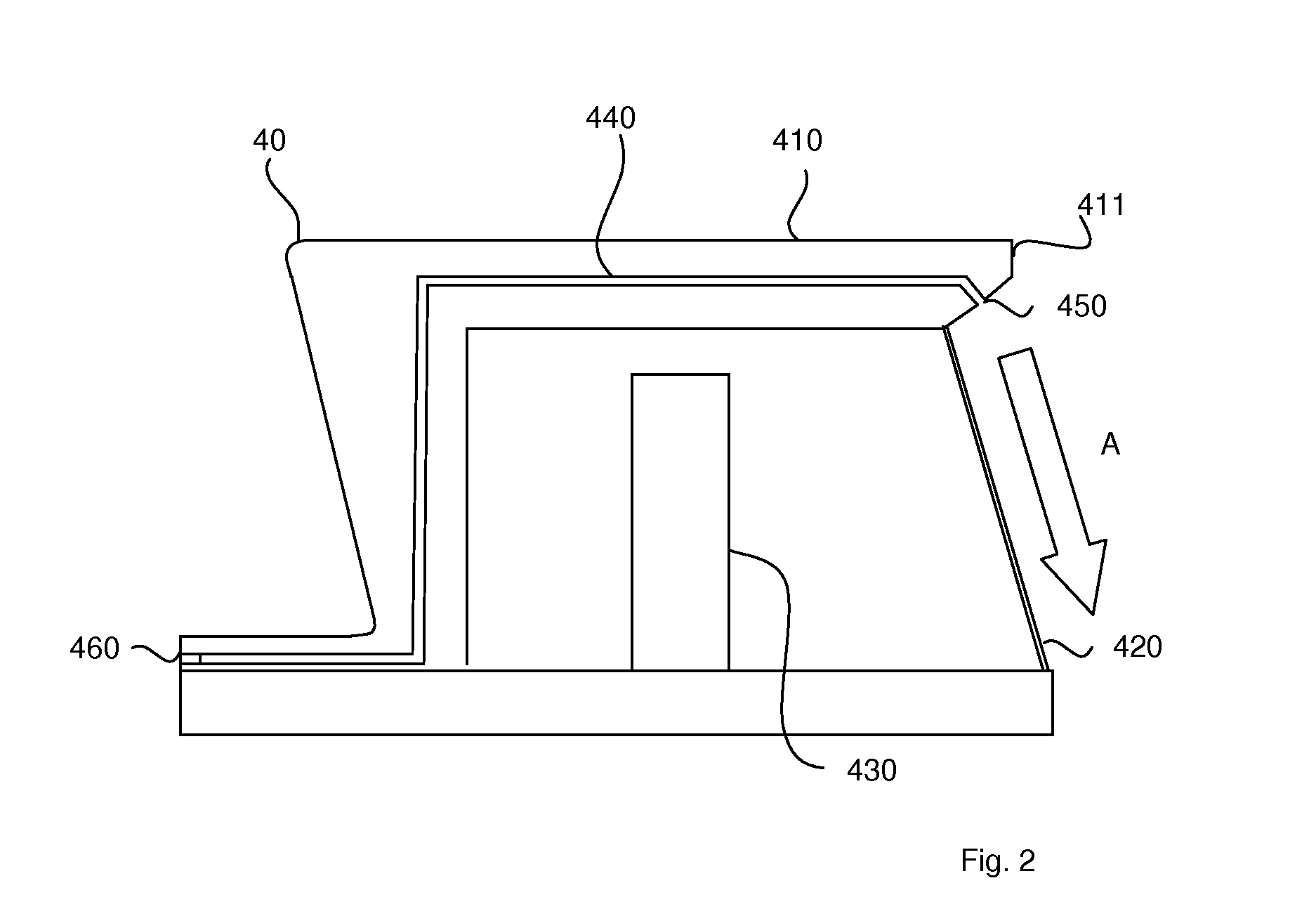
A milking system includes a milking robot with a robot arm for applying teat cups to the teats of an animal, an optical detector (40) for detecting radiation emitted and / or reflected from the animal and a controller. The detector has a housing (410) with a window (420) and a detecting element (430) enclosed in the housing that is sensitive to the emitted or reflected radiation passing through the window. In order to prevent contamination from impacting on the detector window, an airflow arrangement is provided that can be connected to a source of pressurized air and has at least one aperture (411) disposed adjacent the detector window (420) for generating a curtain of air that flows parallel with the surface of the window. The controller controls the generation of the air curtain to coincide with the start of at least one further operation controlled by the controller.

Description

TECHNICAL FIELD[0001]The present invention relates to optical detectors for use in contaminated environments and has particular relevance to optical detectors used in automatic or semiautomatic milking systems, for example, for determining the position of an animal's teats.BACKGROUND[0002]An optical detection arrangement, such as is commonly used in automatic milking systems, typically includes a detector in the form of a diode detector or CCD array camera for detecting radiation that is emitted or reflected from an object of interest, and using the detected radiation to determine the distance between the object and the detector. Some systems may also have a radiation source, for example, a laser, used to illuminate objects of interest with suitable radiation. In most cases, the radiation detector and source, if present, are arranged in a housing behind a screen or window that protects the camera or diode from surrounding pollution. The window may be made of glass or other suitably ...

Claims


Application Information

Patent Timeline
IPC IPC(8): A01J5/01
CPCA01J5/0175
Inventor ANDERSSON, JAN-ERIKHALLSTROM, ANDERS
Owner DELAVAL HLDG AB
Learn More