Method for automated, closed loop cleaning of tanks

a technology of closed loop cleaning and closed loop cleaning, which is applied in the direction of cleaning hollow objects, cleaning processes and utensils, chemistry apparatus and processes, etc., can solve the problems of limited tank capacity, harmful to personnel and the surrounding environment, and tank cleaning, etc., and achieves significant economic valu

Inactive Publication Date: 2013-09-26
CHANTHAVONGSY PEAK +1
View PDF13 Cites 8 Cited by
  • Summary
  • Abstract
  • Description
  • Claims
  • Application Information

AI Technical Summary

Benefits of technology

[0015]In accordance with the method of the present invention, each tank to be cleaned is initially assessed for recoverable fluids, as well as the safest and most efficient cleaning method and best practice for removing residual fluids and cleaning of such tank. Any free drilling mud, other fluid or solids remaining in such tank is first removed and saved; recoverable fluids suitable for reuse or other salvage may have a significant economic value.
[0018]For so-called shale shakers, once it is determined that all recoverable drilling fluids have been removed from sand traps and settling tanks of such shale shakers, flow lines from a rig floor are initially flushed. A hose with one or more nozzles can be used to clean inside such shale shakers and troughs. A hydraulic sump pump, air diaphragm pump or other pump can be beneficially used to return wash water back into a weir tank for re-use. A closed loop washing process is repeated through removal of solids to eliminate the need for additional wash water. Once substantially all solids have been removed from a shale shaker and troughs, a final cleaning / rinse can be performed using a steam cleaning unit.

Problems solved by technology

Caution must typically be taken during storage, use and / or handling of such fluids, since many such drilling fluids and / or associated chemicals or additives can be harmful to personnel and the surrounding environment.
Limited tank capacity on a drilling rig or other location frequently necessitates using the same tanks to store multiple different fluids.
However, because such different types of fluids may not be compatible with one another, it is frequently necessary to clean such tanks before switching out fluids to be stored in such tanks.
Cleaning tanks (including, without limitation, drilling rig or frac tanks) can often prove to be a difficult, expensive and time consuming process.
Personnel are often utilized to manually clean such tanks which can be very physically challenging, especially on hot days when temperatures inside such tanks can be extremely high (and ventilation within such tanks can be very poor).
Prolonged manual cleaning of tanks raises safety concerns, because personnel inside such tanks are frequently exposed to fluid residue, chemicals, toxins and / or contaminants that may be present within such tanks.
After being used, the wash water effluent or other fluid typically contains significant amounts of solids or other contaminants.
As a result, such effluent typically cannot be dumped or otherwise disposed of where the tank is located due to environmental concerns.
Generally, the greater the volume of the wash effluent, the greater the cost of such disposal.
Existing tank cleaning methods can result in dramatic increases in water utilization, chemical use, energy consumption, and waste (including wash effluent) disposal costs.
Such operations can be costly, time consuming, labor intensive and detrimental to the environment by generating excessive amount of wash effluent throughout the course of tank cleaning operations.

Method used


Image

  • Method for automated, closed loop cleaning of tanks
  • Method for automated, closed loop cleaning of tanks

Examples


Embodiment Construction

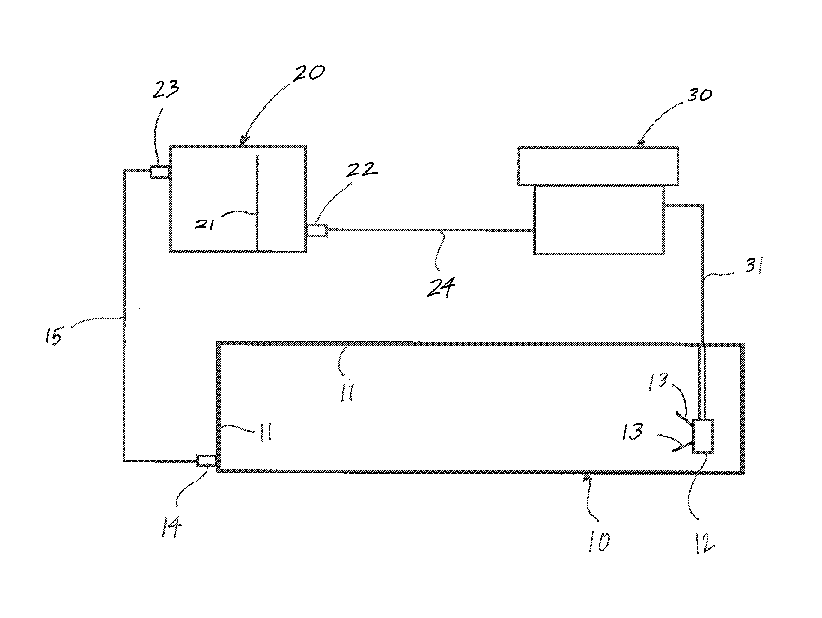
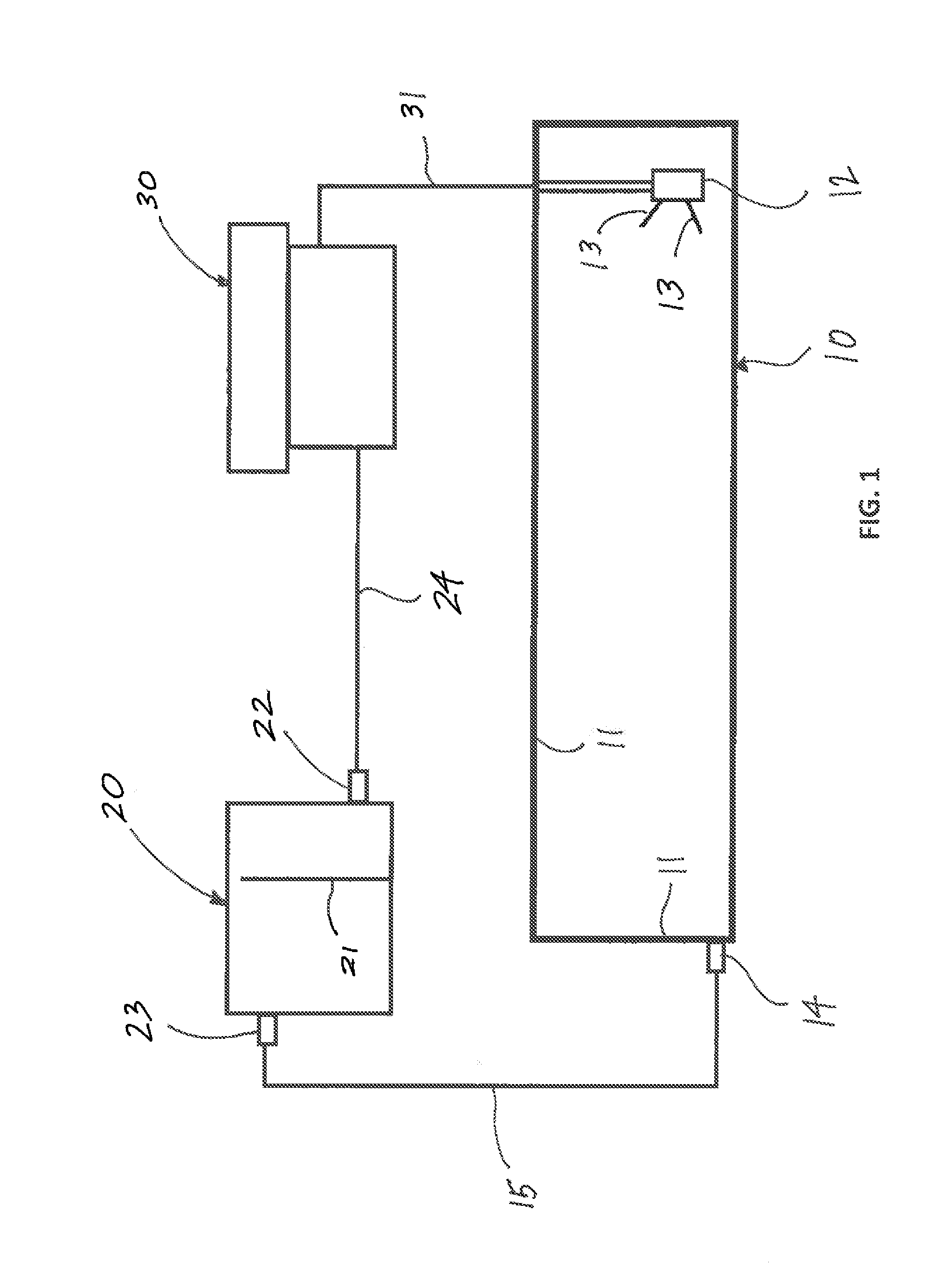
[0023]The present invention comprises a method for cleaning tanks including, without limitation, frac tanks and tanks associated with operations on land-based drilling rigs. The cleaning method of the present invention reduces waste water consumption, cleaning time, and safety risks inherent with existing tank cleaning operations.

[0024]In accordance with the method of the present invention, a tank to be cleaned is initially assessed for recoverable fluids, as well as the safest and most efficient cleaning method and best practice for removing residual fluids and cleaning of such tank. Substantially all drilling mud and / or other fluid remaining in such a tank is first removed and saved; recoverable fluids suitable for reuse or other salvage can be segregated and saved, as such fluids may have economic value.

[0025]Fluids (including residual fluids) present on walls, floors or other internal surfaces of such tank can then removed with a squeegee or other similar method. Such residual f...


PUM


Abstract

A method for cleaning tanks and other containers including, but not necessarily limited to, tanks associated with land-based drilling rigs and / or used in connection with hydraulic fracturing operations. Recoverable liquids and associated solids are first removed from a tank to be cleaned. A cleaning solution is prepared in a weir tank and sprayed into a tank to be cleaned. Sprayed cleaning solution, together with any debris or residue from the tank being cleaned, is pumped back to the weir tank and recycled for further cleaning.

Description

CROSS REFERENCES TO RELATED APPLICATION[0001]Priority of U.S. Provisional Patent Application Ser. No. 61 / 615,522, filed Mar. 26, 2012, incorporated herein by reference, is hereby claimed.STATEMENTS AS TO THE RIGHTS TO THE INVENTION MADE UNDER FEDERALLY SPONSORED RESEARCH AND DEVELOPMENT[0002]NoneBACKGROUND OF THE INVENTION[0003]1. Field of the Invention[0004]The present invention pertains to a method for cleaning tanks and other containers including, but not necessarily limited to, tanks associated with land-based drilling rigs and tanks used in connection with hydraulic fracturing operations.[0005]2. Brief Description of the Prior Art[0006]Tanks, containers and other similar enclosures are commonly used to store fluids that are utilized in any number of different applications. Tanks of varying sizes and shapes are frequently used to store liquids in connection with numerous industries including, but not necessarily limited to, the oil and gas industry.[0007]With respect to oil and ...

Claims


Application Information

Patent Timeline
Patent Type & Authority Applications(United States)
IPC IPC(8): B08B9/093
CPCB08B9/093
Inventor CHANTHAVONGSY, PEAKMARTIN, DALE
Owner CHANTHAVONGSY PEAK
Why Eureka
Try Eureka