
Sealing Device and Method for Sealing a Container Bowl with a Heat Sealing Film

a sealing device and heat sealing technology, which is applied in the field of sealing devices for sealing container bowls with heat sealing films, can solve the problems of deformation, inability to compensate for individual thickness tolerances and position tolerances, and inability to apply uniform and satisfactory sealing pressure to individual container bowls and the heat sealing film resting thereon. , to achieve the effect of enhancing precision, avoiding unwanted alignment tolerances, and high stiffness of construction

Active Publication Date: 2013-09-26
HARRO HOFLIGER VERPACKUNGSMASCHEN
View PDF3 Cites 10 Cited by
  • Summary
  • Abstract
  • Description
  • Claims
  • Application Information

AI Technical Summary

Benefits of technology

The invention provides a sealing method that is more reliable and tolerant of variations in the materials being sealed. The sealing head has a base member and a replaceable sealing plate. The base member has a heating jacket and temperature sensor for precise control of the sealing temperature. The sealing plate is designed to be easily replaced without needing to replace the temperature sensor or heating jacket. This simplifies maintenance and reduces costs.

Problems solved by technology

A problem in this context is that the individual container bowls have thickness tolerances and position tolerances which cannot be compensated by the sealing head that is jointly acting onto the several container bowls.
As a result, there is the risk that individual container bowls and the heat sealing film resting thereon are not subjected to a uniform and satisfactory sealing pressure or that individual container rims that are too thick are excessively melted under pressure that is too high and are thereby deformed too much.
The sealing action can therefore be defective and can lead to undesirable rejects.
A problem here is the high expenditure for the device and the control circuit.
The individual suspension of the container bottom part is complex and cost-intensive wherein an exact adjustment of the controlled contact pressure is required.

Method used


Image

  • Sealing Device and Method for Sealing a Container Bowl with a Heat Sealing Film
  • Sealing Device and Method for Sealing a Container Bowl with a Heat Sealing Film
  • Sealing Device and Method for Sealing a Container Bowl with a Heat Sealing Film

Examples


Embodiment Construction

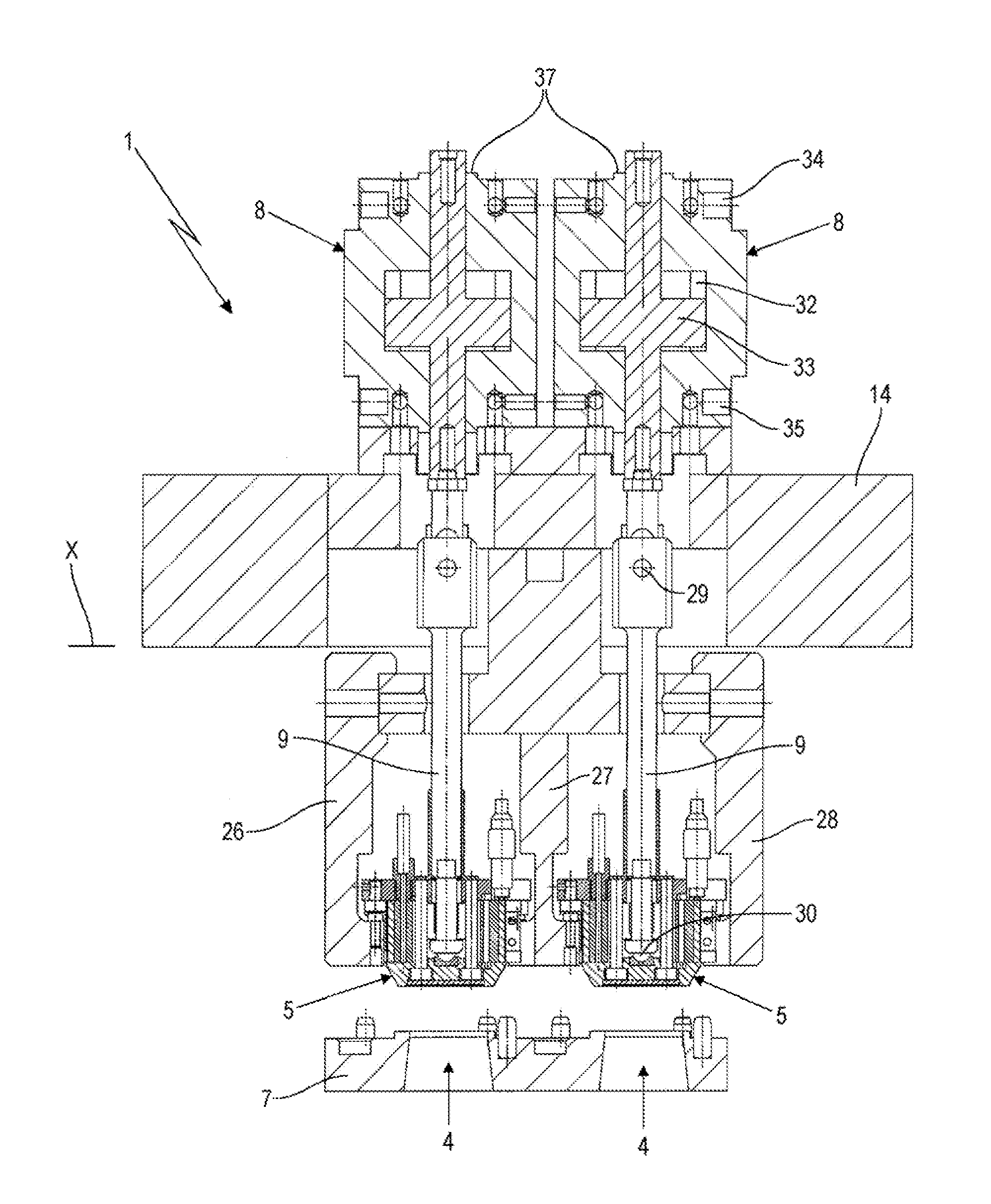
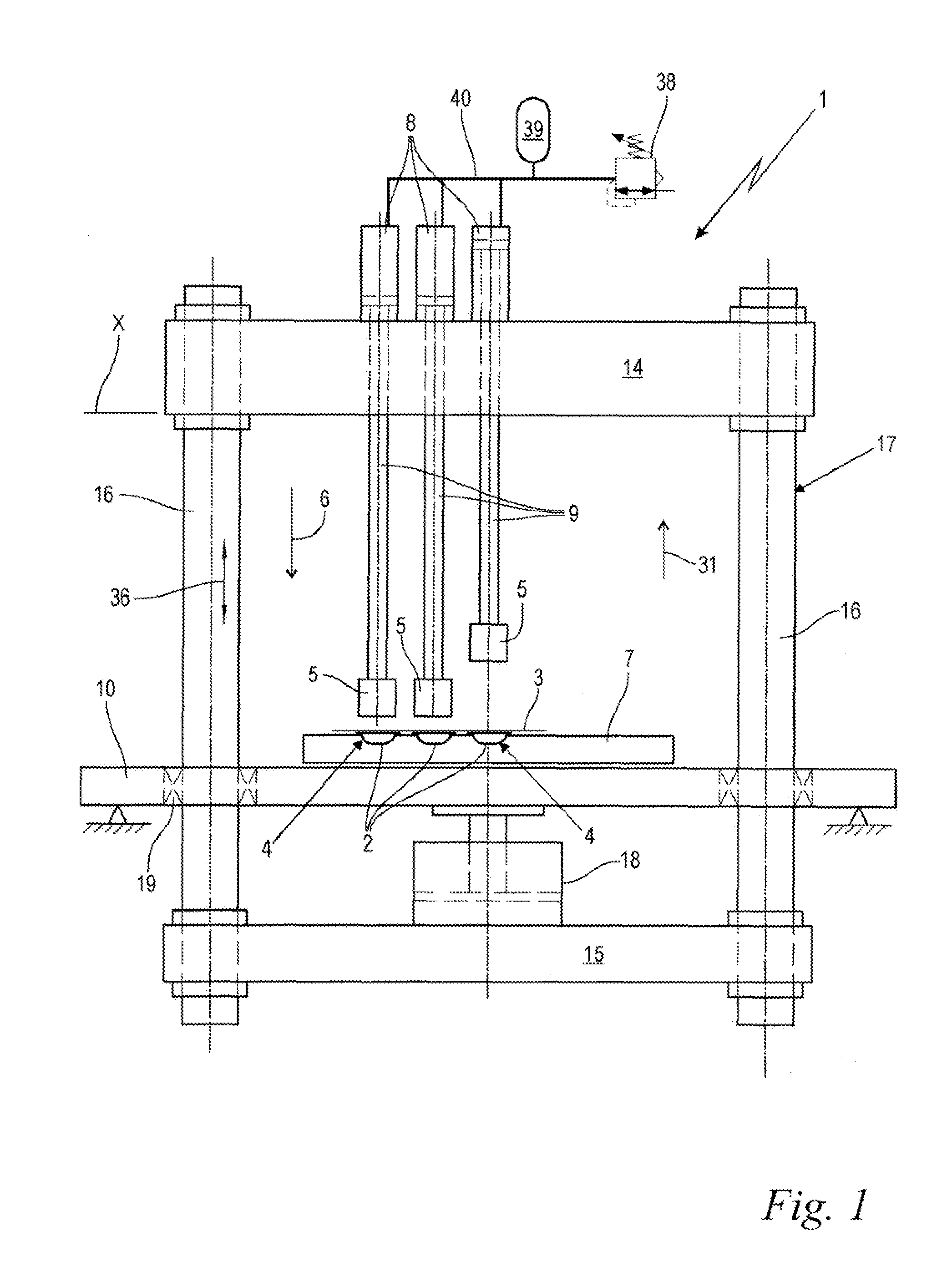
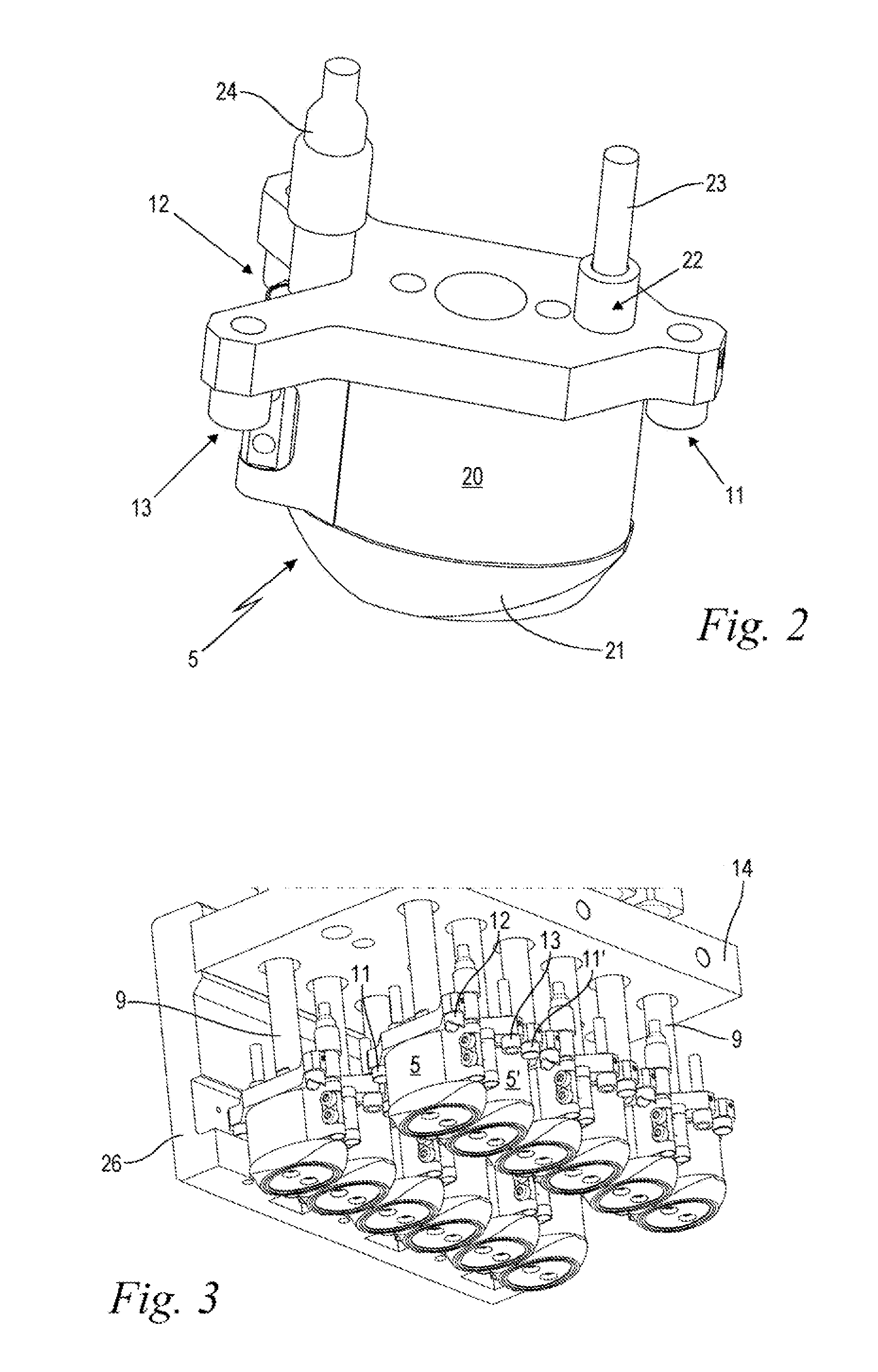
[0031]FIG. 1 shows in a schematic functional illustration as an example the principal configuration and the function of the sealing device 1 according to the invention and of the associated sealing method according to the invention. The sealing device 1 and the associated method are provided for sealing the individual container bowls 2 with a continuous heat sealing film 3 covering several container bowls 2. The sealing device 1 comprises several container receptacles 4 for simultaneously receiving several container bowls 2. In this context, several container receptacles 4 are connected fixedly to each other so that they do not allow relative movement relative to each other on a technically relevant scale. This can be achieved in that individual container receptacles 4 are embodied as individual parts and, for example, are screw-connected, clamped or in other ways fixedly connected to each other. In the illustrated embodiment, a continuous substantially rigid receiving block 7 is pr...


PUM

PropertyMeasurementUnit
Pressureaaaaaaaaaa

Abstract

A sealing device for sealing container bowls with a heat sealing film has several sealing heads each correlated with one container receptacle. The sealing heads are movable in a sealing stroke direction relative to the container receptacles that are connected fixedly to each other. The sealing heads are forced with pretension into a rest position by spring elements in the sealing stroke direction against a stop, each sealing head having one stop associated therewith. For simultaneous sealing of the heat sealing film onto the several container bowls, a spring support, on which the spring elements are jointly secured, is moved together with the sealing heads so far in the sealing stroke direction relative to the container receptacles that the sealing heads upon impacting on the container receptacles correlated therewith, with interposition of the container bowls and the heat sealing film, are lifted off their stops against the pretension.

Description

BACKGROUND OF THE INVENTION[0001]The invention concerns a sealing device for sealing container bowls with a heat sealing film, the sealing device comprising several container receptacles for simultaneous receiving of several container bowls as well as several sealing heads associated each with a container receptacle, wherein the several sealing heads for simultaneous sealing of the heat sealing film onto the several container bowls are movable in a sealing stroke direction relative to the container receptacles, wherein the several container receptacles are fixedly connected to each other and in particular combined in a common receiving block, and wherein the several sealing heads in a rest position are forced with pretension by means of a spring element, respectively, in the sealing stroke direction against a stop, each sealing head having one stop associated therewith. The invention further relates to an associated method for sealing such container bowls with a heat sealing film.[0...

Claims


Application Information

Patent Timeline
IPC IPC(8): B65B7/00
CPCB65B51/14B29C66/961B65B25/008B65B7/00B29C65/18B29C65/7841B29C66/112B29C66/131B29C66/53461B29C66/81463B29C66/8161B29C66/8167B29C66/8242B29C66/8322B29C66/8432B29C66/91212B29C66/91231B29C66/91421B65B7/16B29C66/83221B29C66/849B29C66/876B29L2011/0041B29L2031/7164
Inventor STRAUB, KLAUSEGELKRAUT, UDO
Owner HARRO HOFLIGER VERPACKUNGSMASCHEN
Learn More