Fluid evaporator for an open fluid reservoir

a technology of fluid evaporator and open fluid, which is applied in the direction of evaporation, lighting and heating apparatus, separation processes, etc., can solve the problems of contaminates and un-evaporated droplets, uncontrolled release of contaminates into surrounding environments, and unwanted deposition of contaminates in surrounding areas

Active Publication Date: 2013-09-26
HEARTLAND WATER TECH INC
View PDF8 Cites 16 Cited by
  • Summary
  • Abstract
  • Description
  • Claims
  • Application Information

AI Technical Summary

Problems solved by technology

For the purposes of this application, however, the exact fluid, contaminant, and source of contaminant is not particularly relevant, and so the terms water and contaminant will be used generically to include any fluid and matter, respectively, that one would desire to treat or purify, unless otherwise clearly indicated.
A problem with these misting-types of reservoir evaporation systems, however, is that under non-ideal conditions the contaminates and un-evaporated droplets may be borne by winds away from the reservoir and settle out at nearby areas rather than in the reservoir.
This could lead to unwanted deposition of the contaminates in surrounding areas, such as residential or other built-up areas, or uncontrolled release of the contaminates into surrounding environments, all of which are forms of multi-media pollution.
Additionally, such systems frequently require a supply of high pressure to force the effluent through a nozzle and adequately aerosolize the effluent into the surrounding air.
In addition to the potential of causing multi-media pollution, another drawback to these systems is the need to use moving parts, which can frequently break or become jammed through buildup of scale from the contaminants.
Additionally, the inclusion of a high pressure air or liquid supply in each of these reservoir evaporator systems can increase complexity, cost, and maintenance requirements.
These designs, while overcoming the problem of drift to surrounding areas, may often require extensive maintenance to keep the evaporation surfaces free of contaminant buildup and often require complex mechanical and / or effluent transfer systems for dispersing the effluent onto the evaporation surfaces.

Method used


Image

  • Fluid evaporator for an open fluid reservoir
  • Fluid evaporator for an open fluid reservoir
  • Fluid evaporator for an open fluid reservoir

Examples


Embodiment Construction

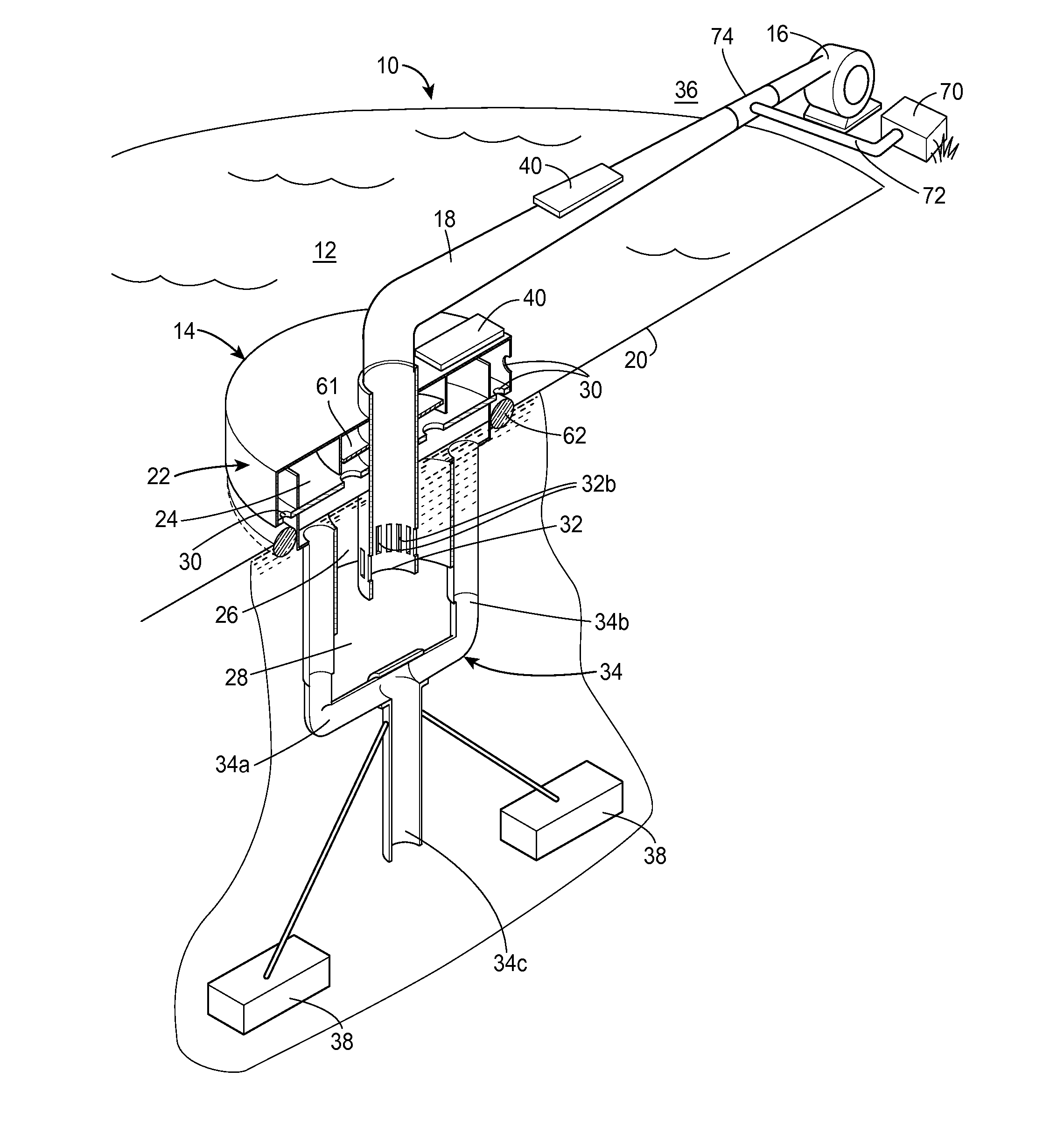
[0029]Turning now to the drawings, FIG. 1 shows a reservoir evaporation system 10 being used for evaporating liquid from an open reservoir of effluent 12 according to one aspect. As exemplified in FIG. 1, the reservoir may be an outdoor body of fluid, such as a pond, lake, retention pond, or dry pond. The reservoir, however, is not limited to any particular type of reservoir, and could include holding tanks, settling vessels, etc. Rather, the evaporation systems 10 disclosed herein may be used with any body of open water or other type of fluid. In one anticipated use, the reservoir may be a collection pond for effluent 12 including acid mine runoff. For simplicity, the following detailed description refers to effluent, but it is understood that the principles described herein may be used for evaporating uncontaminated fluids in the same manner and the disclosure is not to be limited to only use with contaminated fluids.

[0030]The reservoir evaporation system 10 includes a fluid evapo...


PUM


Abstract

A reservoir evaporation system for evaporating fluid from an open reservoir of effluent containing a contaminant includes a fluid evaporator, an air pump, and an air supply conduit functionally connecting the fluid evaporator with the air pump. The fluid evaporator includes a vessel adapted to be positioned in an operative position partially submerged on the top surface of the effluent in the reservoir with a lower chamber submerged in the effluent and an upper chamber extending above the top surface of the effluent. In operation, air from the air pump mixes with the effluent inside the fluid evaporator and subsequently is discharged through exhaust openings. A fluid discharge pipe can also simultaneously discharge aerated effluent back down into the reservoir. Fluid is thereby separated from the effluent in the lower chamber by evaporation in a controlled manner that minimizes spread of contaminants to surrounding environments by wind.

Description

BACKGROUND[0001]1. Field of the Disclosure[0002]The present invention relates to devices and methods for evaporating fluids from an open fluid reservoir, which in some applications may be used to accelerate the rate of concentration of suspended solids therein with or without the feature of promoting or maintaining aerobic conditions within the open fluid reservoir.[0003]2. Background Art[0004]Water and other fluids often accumulate various contaminants, and it is often desirable or necessary to separate the fluid from the contaminant to meet various purity targets or reduce the volume of liquid within an open reservoir, which may be necessary for practical, legal, or other reasons. Such contaminants may include, for example, salts, sulfur, heavy metals, suspended soils, human or animal waste, oils, fertilizers, pharmaceuticals, acid and any other undesirable matter as would be apparent to a person of skill in the art. The sources for contaminated fluids, also called effluent, are m...

Claims


Application Information

Patent Timeline
Patent Type & Authority Applications(United States)
IPC IPC(8): B01D1/00
CPCB01D1/0005B01D1/30C02F1/10B01D1/14C02F1/043Y02W10/37
Inventor DUESEL, JR., BERNARD F.RUTSCH, MICHAEL J.CLERKIN, CRAIG
Owner HEARTLAND WATER TECH INC
Why Eureka
Try Eureka