Lubrication system and a working machine

Active Publication Date: 2013-09-26
WARATAH OM
View PDF4 Cites 9 Cited by
  • Summary
  • Abstract
  • Description
  • Claims
  • Application Information

AI Technical Summary

Benefits of technology

[0006]It is an aim of the present disclosure to introduce a novel lubrication system for a work implement at the end of the boom assembly of a working machine, by means of which the lub

Problems solved by technology

Furthermore, thanks to the lubrication system, the interval for adding lubricant can be made long, since the size of the lubricant reservoir of the lubricant sourc

Method used


Image

  • Lubrication system and a working machine
  • Lubrication system and a working machine
  • Lubrication system and a working machine

Examples


Embodiment Construction

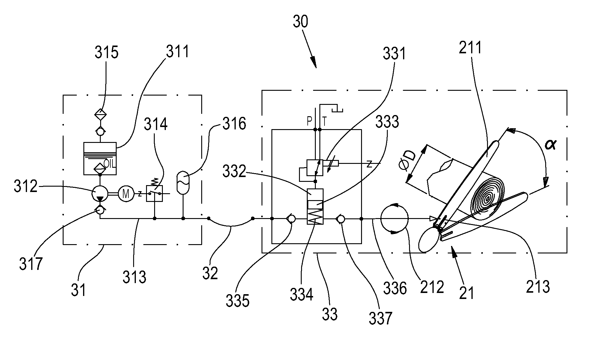
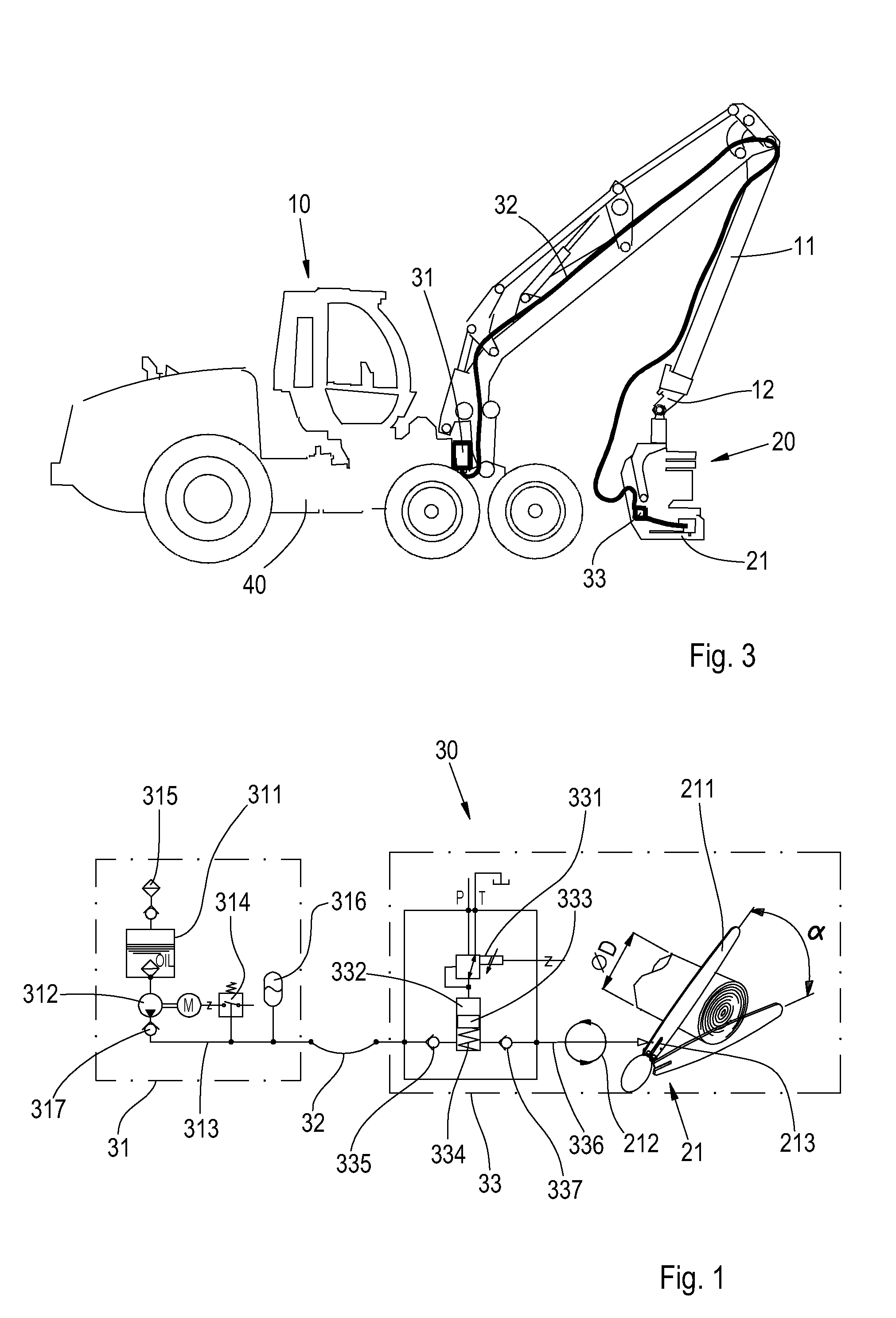
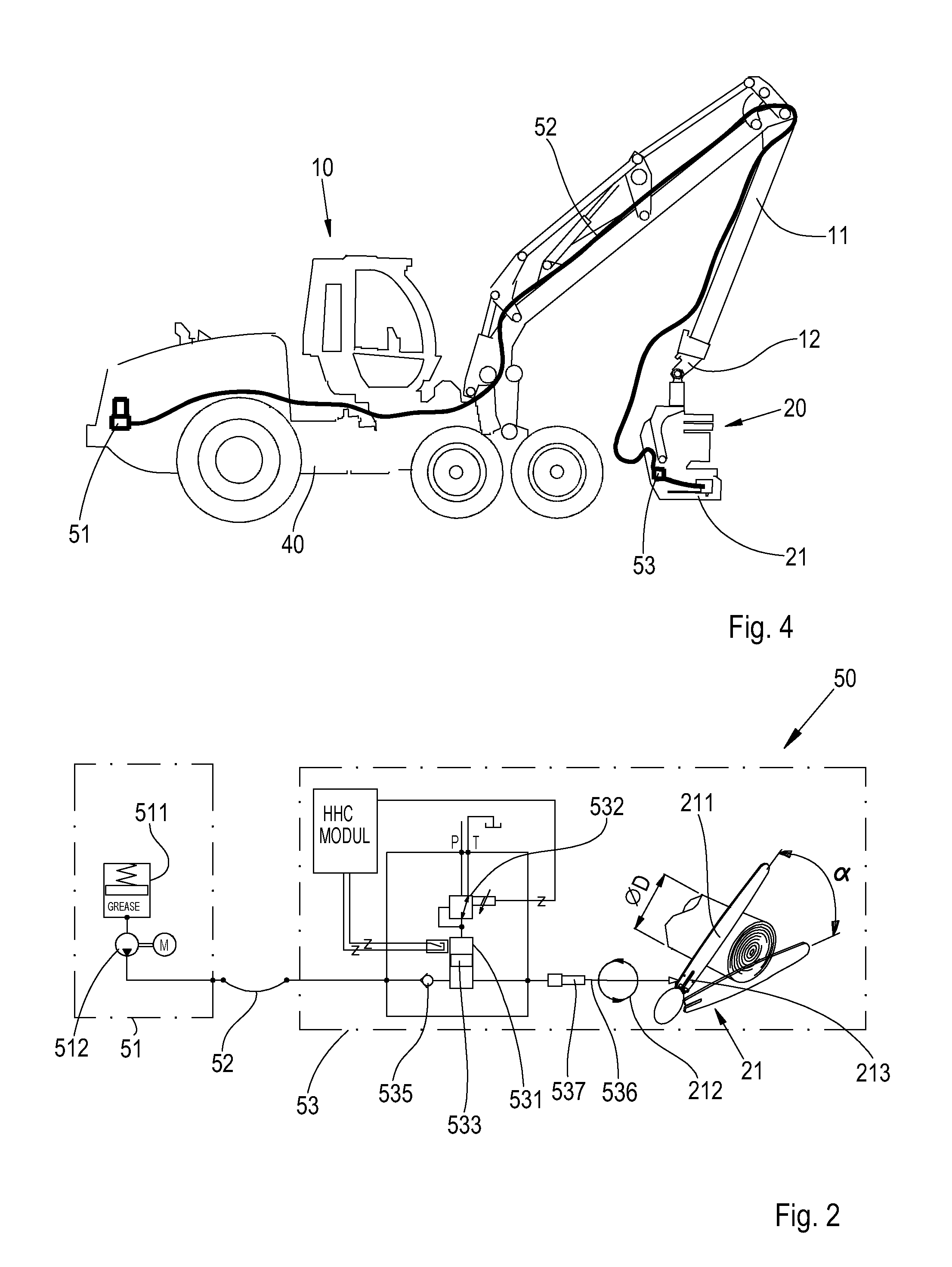
[0026]FIG. 1 shows schematically an embodiment of a lubrication system. The lubrication system of FIG. 1 can be installed, for example, in a forest machine 10 shown in FIG. 3, where the chain saw 21 in the harvester head 20 at the end 12 of a boom assembly 11 is lubricated with oil. The lubrication system 30 of FIG. 1 comprises a lubricant source 31, a main line 32 and a dispensing unit 33. In the embodiment of FIG. 2, the lubricant source 31 is placed in the base machine 40, and the dispensing unit 33 is placed in the harvesting head 20.

[0027]The lubricant source 31 comprises an oil reservoir 311 for oil used as lubricant, and a feeder pump 312 for pumping the oil. In an application of the type shown in FIG. 1, an advantageous location for the oil reservoir 311 and the feeder pump 312 is, as shown in FIG. 3, for example between the swivelling device and the tilting cylinder of the boom assembly 11. The volume of the oil container 311 is approximately 20 litres, wherein it is suffic...


PUM


Abstract

The present disclosure relates to a lubricating system for lubricating an implement to be lubricated in the boom system of a working machine, the system comprising a lubricant source which can be installed in a base machine for the working machine and coupled to the implement to be lubricated. The lubricating system further comprises a dispensing unit which can be connected to the implement to be lubricated, for dispensing lubricant to the implement to be lubricated. The present disclosure also relates to a working machine comprising a lubricating system.

Description

[0001]The present application claims priority to Finnish Patent Application No. 20125312 which was filed on 20 Mar. 2012 and is hereby incorporated by reference herein.FIELD OF THE DISCLOSURE[0002]The present disclosure relates to a lubrication system for lubricating a work implement in a boom assembly of a working machine. The present disclosure also relates to a working machine, the working machine comprising a boom assembly, and the boom assembly comprising at least one work implement to be lubricated.BACKGROUND OF THE DISCLOSURE[0003]Document WO 2008 / 141411 discloses a lubricating system for lubricating the chain saw of a felling head at the end of a boom assembly of a forest machine. This system comprises a grease reservoir, a grease feeder and a grease pump, which are all placed in connection with the engine compartment of the base machine. The feeder is connected to the grease pump in such a way that it supplies grease from the grease reservoir via the inlet of the grease pum...

Claims


Application Information

Patent Timeline
IPC IPC(8): F16N7/38
CPCF16N7/38B27B17/12B27B17/0091A01G23/091
Inventor KETTUNEN, VEIKKOHANNONEN, MIKA
Owner WARATAH OM
Why Eureka
Try Eureka