
Configurable multi-mode pwm controller

a controller and multi-mode technology, applied in the direction of electric variable regulation, process and machine control, instruments, etc., can solve the problems of delay in the design cycle and increase the cos

Inactive Publication Date: 2013-09-26
MICREL
View PDF4 Cites 45 Cited by
  • Summary
  • Abstract
  • Description
  • Claims
  • Application Information

AI Technical Summary

Benefits of technology

This patent describes a type of power supply called a switching regulator that is commonly used to convert voltage levels for integrated circuits. The regulator uses power switches to control the output voltage to maintain a constant level. The patent describes a specific method called pulse width modulation (PWM) to control the duty cycle of the power switches. The technical effect of this patent is to provide a more efficient and precise method for controlling the output voltage of a switching regulator.

Problems solved by technology

Changing the controller integrated circuit often involves changing the PC board design which leads to increase cost and causes delay in the design cycle.

Method used


Image

  • Configurable multi-mode pwm controller
  • Configurable multi-mode pwm controller
  • Configurable multi-mode pwm controller

Examples


Embodiment Construction

[0014]The invention can be implemented in numerous ways, including as a process; an apparatus; a system; and / or a composition of matter. In this specification, these implementations, or any other form that the invention may take, may be referred to as techniques. In general, the order of the steps of disclosed processes may be altered within the scope of the invention.

[0015]A detailed description of one or more embodiments of the invention is provided below along with accompanying figures that illustrate the principles of the invention. The invention is described in connection with such embodiments, but the invention is not limited to any embodiment. The scope of the invention is limited only by the claims and the invention encompasses numerous alternatives, modifications and equivalents. Numerous specific details are set forth in the following description in order to provide a thorough understanding of the invention. These details are provided for the purpose of example and the inv...


PUM


Abstract

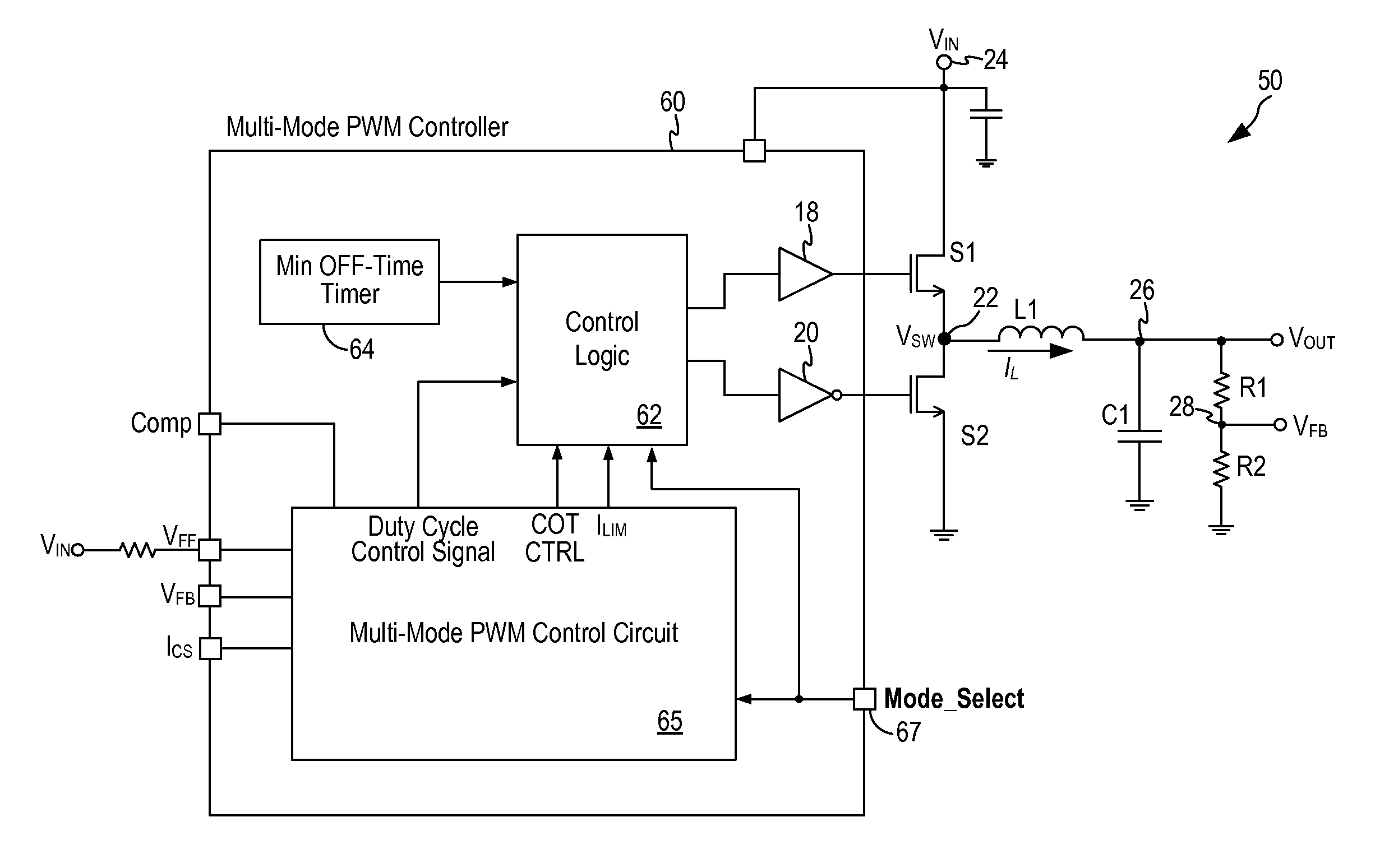
A multi-mode pulse width modulation (PWM) controller for a buck switching regulator includes a multi-mode PWM control circuit where the PWM control circuit is configured to operate in one of multiple control schemes selectable by a mode select signal. In one embodiment, the multi-mode PWM control circuit incorporates a peak current mode control scheme, a voltage mode control scheme, and a valley current mode control scheme. In another embodiment, the multi-mode PWM control circuit further incorporates a constant ON-time control scheme.

Description

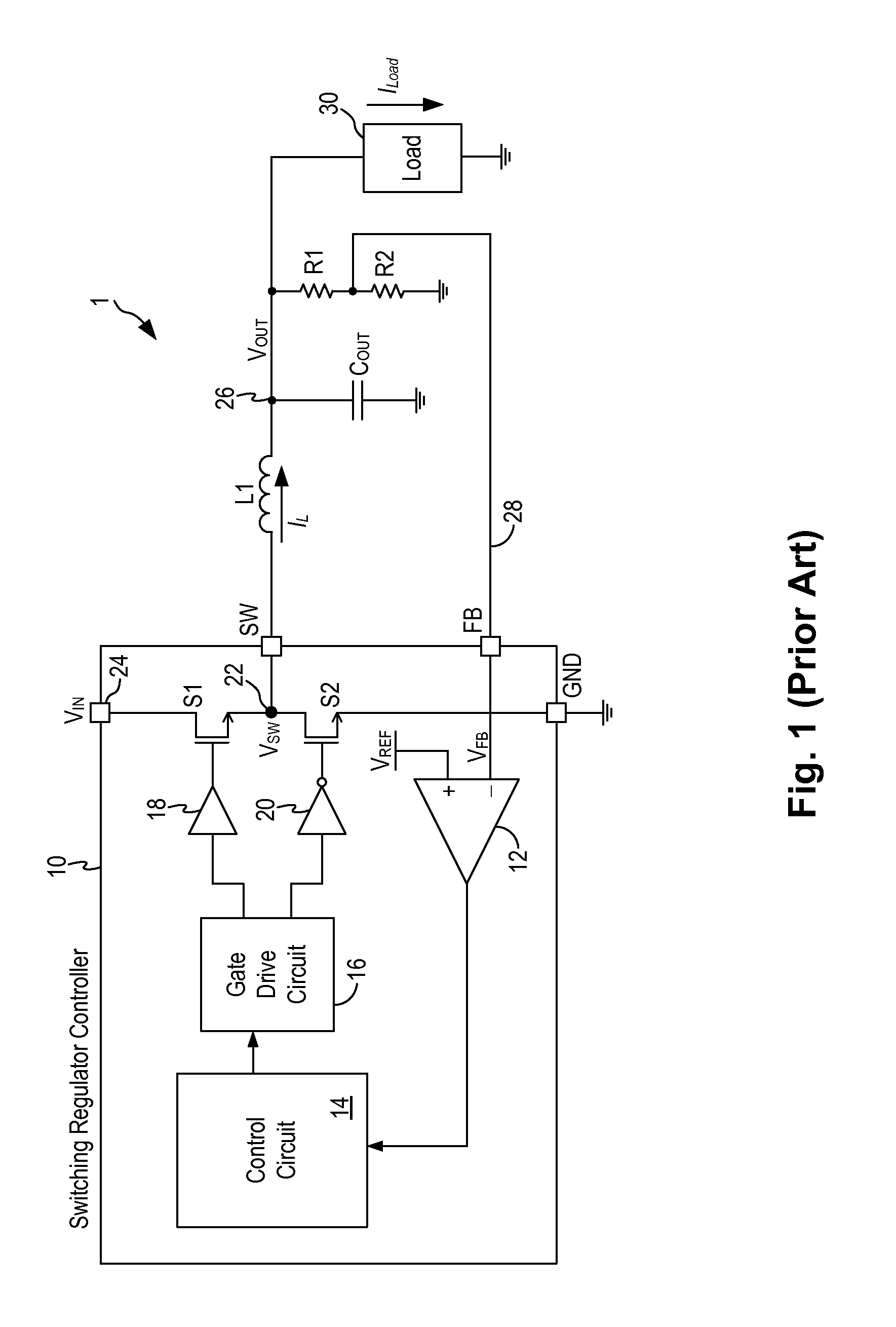
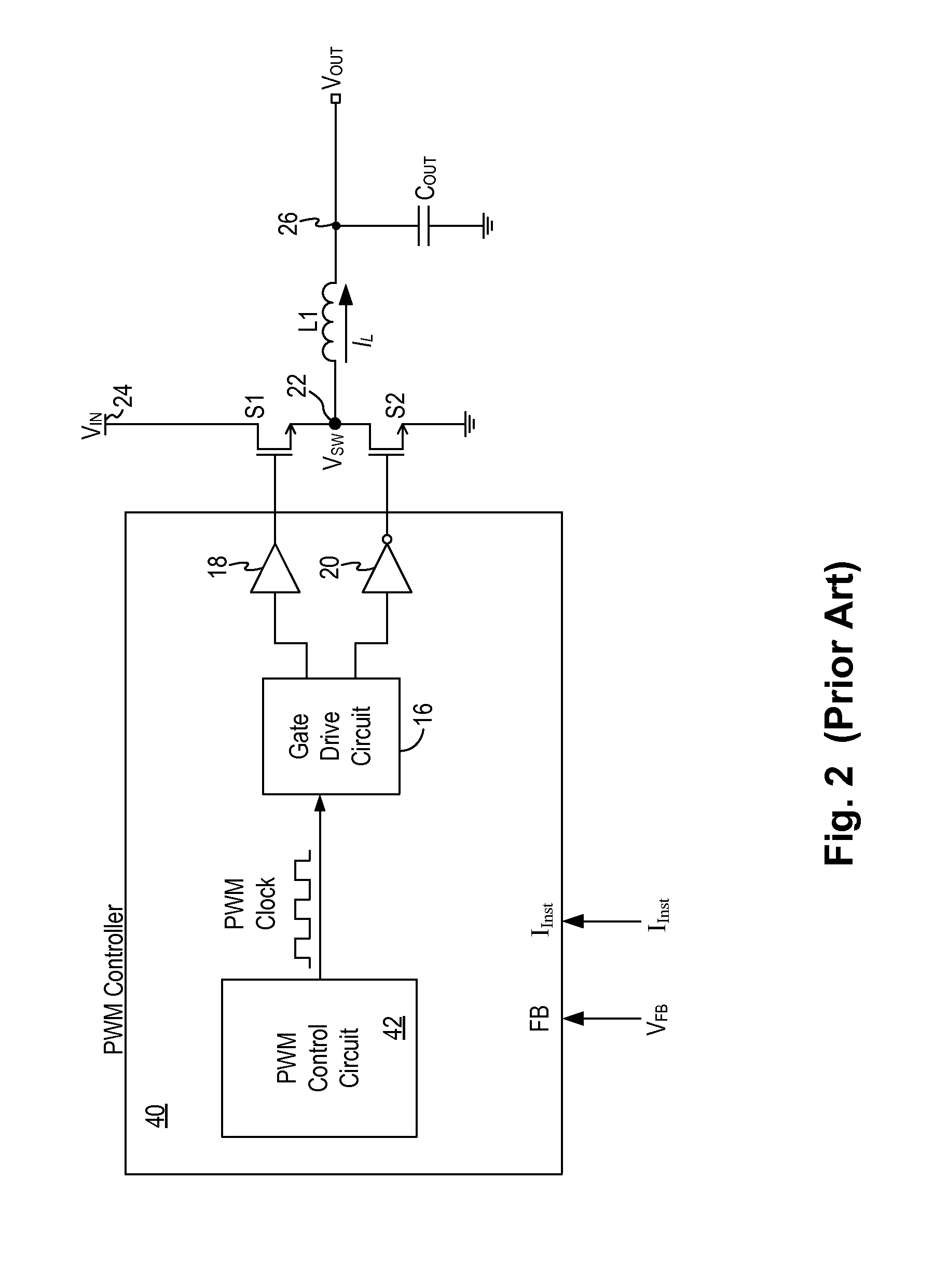
CROSS REFERENCE TO OTHER APPLICATIONS[0001]This application claims priority to U.S. Provisional Patent Application No. 61 / 615,058 entitled CONFIGURABLE MULTI-MODE PWM CONTROLLER filed Mar. 23, 2012, which is incorporated herein by reference for all purposes.BACKGROUND OF THE INVENTION[0002]Switch mode power supplies or switching regulators, also referred to as DC-to-DC converters, are often used to convert an input supply voltage to a desired output voltage at a voltage level appropriate for the internal circuitry of an integrated circuit. For example, a 5 volts supply voltage provided to an integrated circuit may need to be reduced to 2.8 volts on the IC chip to operate the internal circuitry on the chip. A switching regulator provides power supply function through low loss components such as capacitors, inductors, and transformers, and power switches that are turned on and off to transfer energy from the input to the output on cycle by cycle basis. A feedback control circuit is us...

Claims


Application Information

Patent Timeline
Patent Type & Authority Applications(United States)
IPC IPC(8): G05F1/10
CPCG05F1/10H02M3/1588H02M1/0025Y02B70/10
Inventor KALJE, NITINIZADINIA, MANSOUR
Owner MICREL
Learn More