

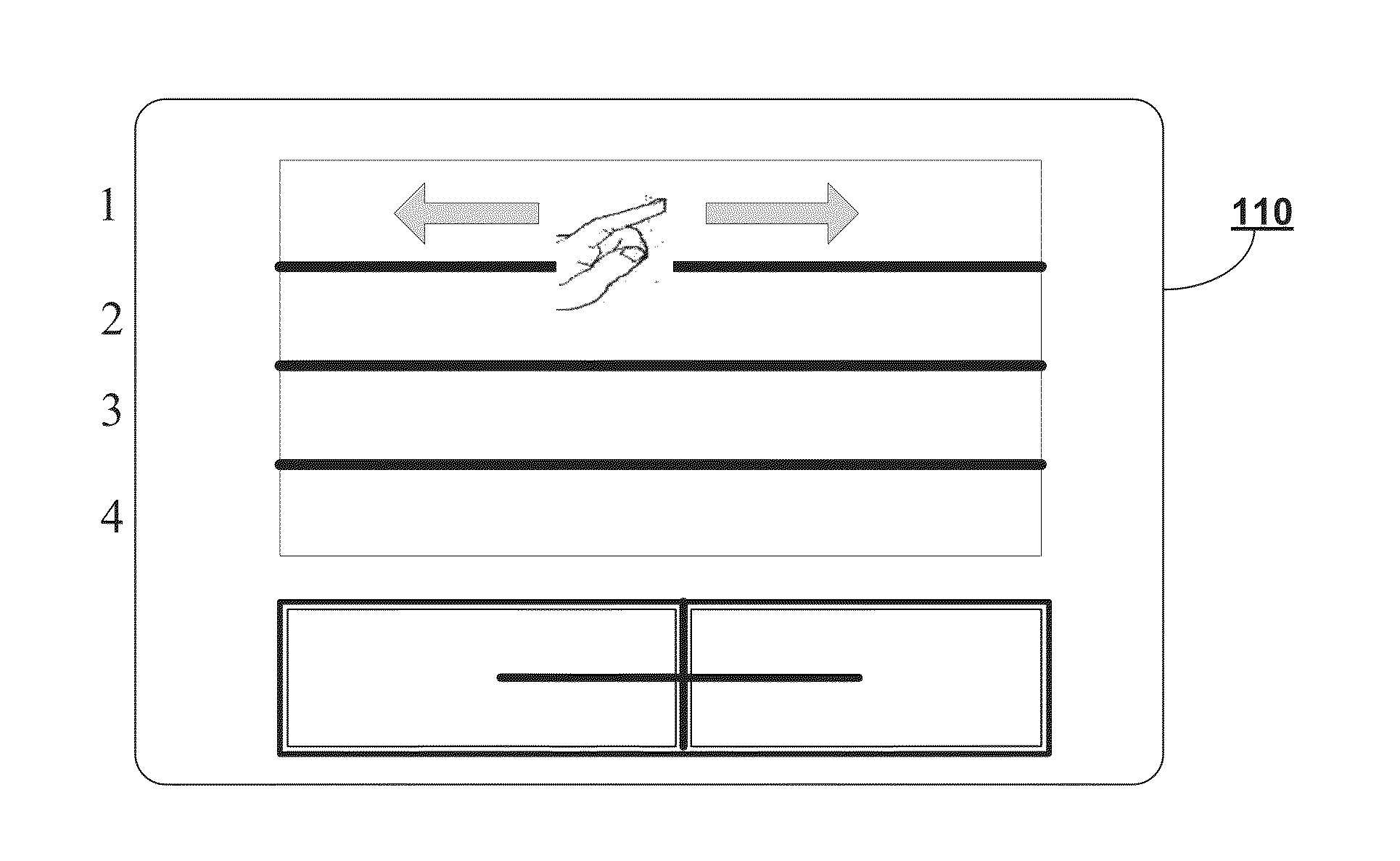
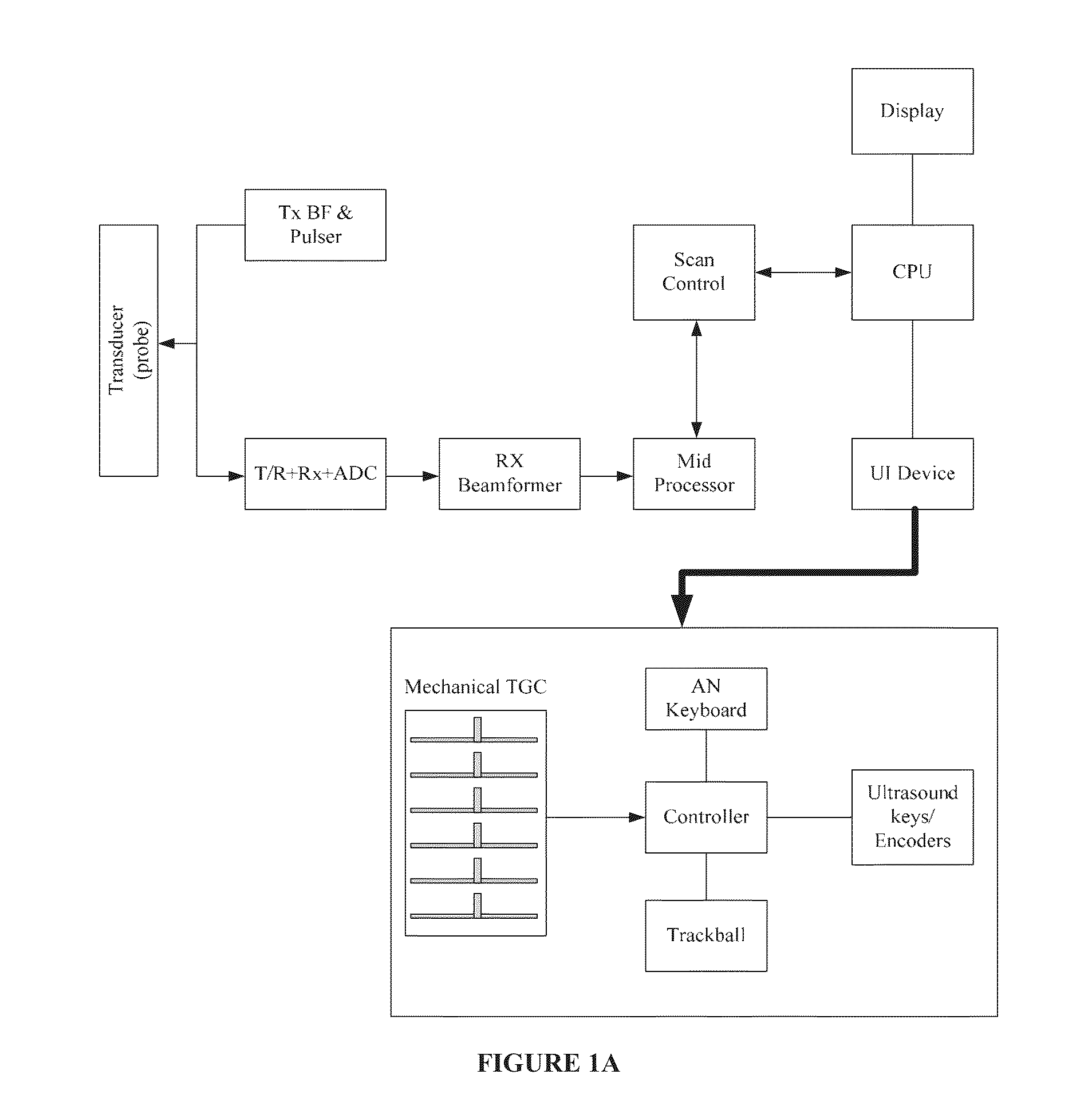
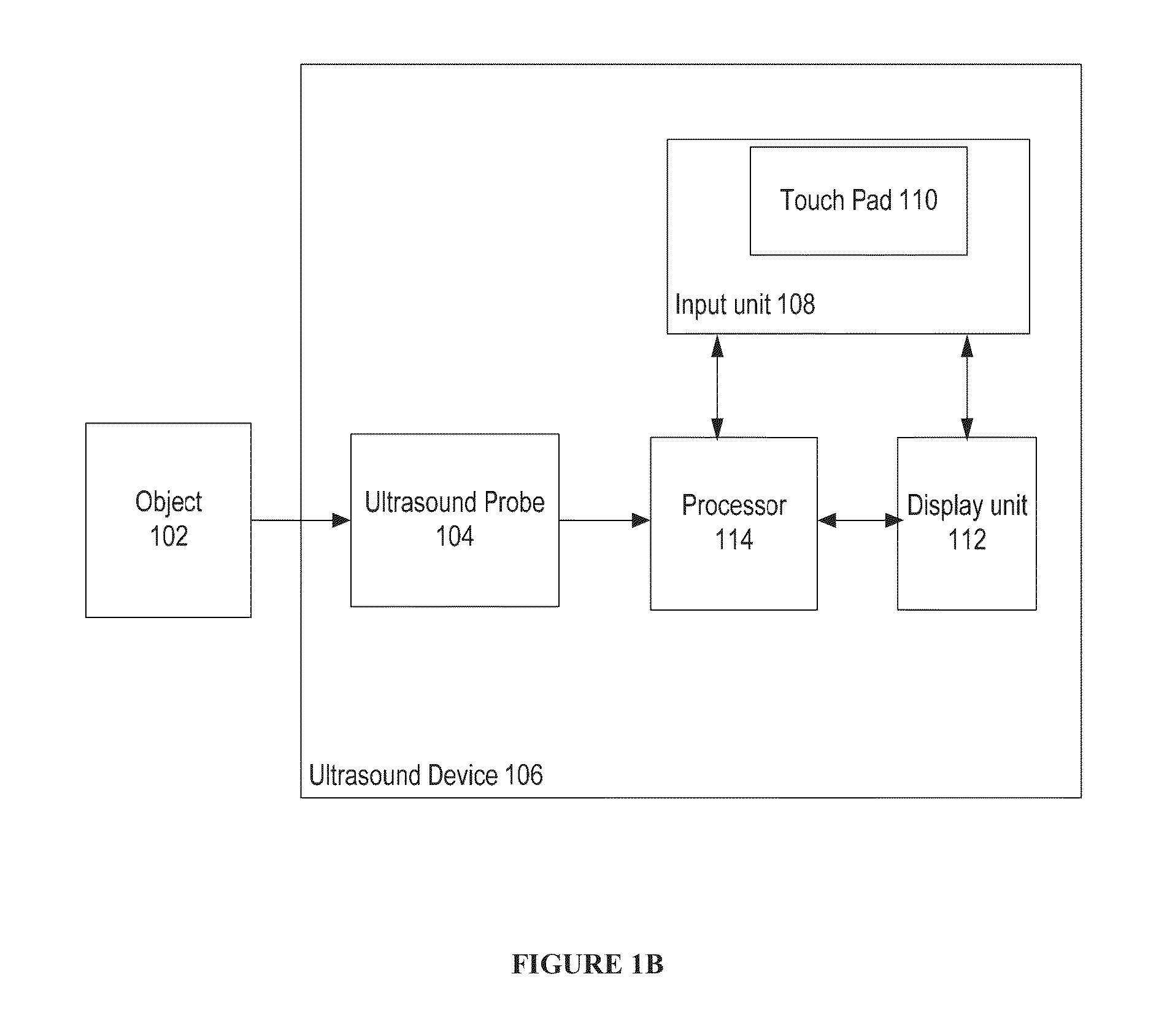
Ultrasound device and method thereof
a technology of ultrasound device and ultrasound tube, which is applied in the field of medical devices, can solve the problems of high cost and complexity of the system, the number of potentiometers in the range of regions that can be controlled, and the vulnerability of traditional potentiometers present in existing ultrasound devices to liquid, dust, gel ingress, etc., and achieve the effect of facilitating the user to adjust the image gain
- Summary
- Abstract
- Description
- Claims
- Application Information
AI Technical Summary
Benefits of technology
Problems solved by technology
Method used
Image

Examples
Embodiment Construction
[0014]The foregoing has broadly outlined the features and technical advantages of the present invention in order that the detailed description of the disclosure that follows may be better understood. Additional features and advantages of the disclosure will be described hereinafter which support the claims of the disclosure. It should be appreciated by those skilled in the art that the conception and specific embodiment disclosed may be readily utilized as a basis for modifying or designing other structures for carrying out the same purposes of the present invention. It should also be realized by those skilled in the art that such equivalent constructions do not depart from the spirit and scope of the disclosure as set forth in the appended claims. The novel features which are believed to be characteristic of the disclosure, both as to its organization and method of operation, together with further objects and advantages will be better understood from the following description when ...
PUM
 Abstract
Description
Claims
Application Information