Throwable camera and network for operating the same

a technology which is applied in the field of operating network and operating camera, can solve the problems of inability to adapt to the environment, and inability to change its own trajectory, so as to improve imagery and improve imagery

Active Publication Date: 2013-09-26
HOLLINGER STEVEN J
View PDF26 Cites 118 Cited by
  • Summary
  • Abstract
  • Description
  • Claims
  • Application Information

AI Technical Summary

Benefits of technology

[0071]In another embodiment, the camera of this invention has a flying-disc shaped housing, a camera aperture on the underside of the housing with an outward and downward view aligned along the minor axis, and an orientation sensor to determine the orientation of the minor axis; the camera being improved in response to aerodynamic forces over a spherical camera and thereby rendered capable of providing improved imagery viewing downward over the course of its trajectory.
[0072]In another embodiment, the camera of this invention has a flying-disc shaped housing, an orientation sensor to determine the orientation of the minor axis, and a camera aperture on the perimeter of the housing surface with an outward view aligned on a perpendicular to the minor axis; the camera being improved in response to aerodynamic forces over a spherical camera and thereby rendered capable of providing improved imagery along the plane of the landscape in its airborne trajectory.
[0073]In another embodiment, the camera of this invention has a prolate spheroid shaped housing, a camera aperture on the forward housing surface with an outward view aligned along the major axis, and an orientation sensor to determine the orientation of the major axis; the camera being improved in response to aerodynamic forces over a spherical camera and thereby rendered capable of providing improved imagery forward of its position in flight.
[0074]In another embodiment, the camera of this invention has a prolate spheroid shaped housing, an orientation sensor to determine the orientation of the major axis, and a camera aperture on the perimeter of the housing surface with an outward view aligned on a perpendicular to the major axis; the camera being improved in response to aerodynamic forces over a spherical camera and thereby rendered capable of providing improved imagery at either side of, below and above its airborne trajectory.
[0075]In another embodiment, the camera of this invention has a torus shaped housing, a camera aperture on the housing surface with an outward view aligned in parallel to the minor axis, and an orientation sensor to determine the orientation of the minor axis; the camera being improved in response to aerodynamic forces over a spherical camera and thereby rendered capable of providing improved imagery at either side of its airborne trajectory.
[0076]In another embodiment, the camera of this invention has a torus shaped housing, an orientation sensor to determine the orientation of the minor axis, and a camera aperture on the perimeter of the housing surface with an outward view aligned on a perpendicular to the minor axis; the camera being improved in response to aerodynamic forces over a spherical camera and thereby rendered capable of providing improved imagery forward, under and behind its position in flight.

Problems solved by technology

This resilient object is further disadvantaged by its inability to change its own trajectory.
The inflatable housing and cubic shape of the preferred embodiment present impractical aerodynamic impediments with respect to drag if a pitched or projected airborne trajectory is desired.
As with the resilient object of patent GB2444391, this ball is disadvantaged by its inability to store and analyze successive frames of captured image data.
The ball is further disadvantaged by its inability to capture successive frames of image data captured while spinning or precessing past a ground-based subject in order to produce a meaningful video stream.
This ball is further disadvantaged by its inability to change its own trajectory.
This patent is disadvantaged by requiring external surface-mounted fins to ensure that the camera provides images from a desirable orientation.
This patent is disadvantaged by requiring an external surface-mounted aerodynamic tail to ensure that the camera provides images from a desirable orientation.
Golf ball dimples produce an undesirable drag at lower windspeeds.
Similarly, the rigid ridges on the upper surface of a Frisbee flying disc produce a desirable increase in lift over a significant portion of the disc's airborne trajectory, but produce an undesirable increase in drag at other portions of the disc's trajectory.
Such balls are disadvantaged by an inability to purposefully control their trajectory.
Projectile cameras of prior art are limited in their ability to generate images acquired in all directions from a single viewpoint, at one moment in time.
Such a limitation makes difficult, for example, the capture of a spherical panoramic video from a central point of view surrounded in all directions by moving objects.
Cameras of prior art, including examples of camera networks, are further disadvantaged by cumbersome camera housings, complex mechanics necessary for locomotion or flight, and costly guidance technology necessary for self-sustained flight.
Prolate spheroid-shaped balls are generally more difficult to throw on a stable axis-forward trajectory than spheres and oblate spheroids because the wrist and fingers must provide spin about the longitudinal axis for rotational stability while the arm, shoulder and body enter an axis-forward motion.
As size is reduced, a prolate spheroid shaped ball is increasingly more difficult to throw because the fingers and wrist must more rapidly express a spin on the exterior surface of the ball around its longitudinal axis while maintaining alignment of the longitudinal axis as it is projected in forward motion.
Cameras of prior art mounted on flying discs have been unable to provide smooth tracking images and video across the landscape, while spinning through the trajectory.

Method used


Image

  • Throwable camera and network for operating the same
  • Throwable camera and network for operating the same
  • Throwable camera and network for operating the same

Examples


Embodiment Construction

[0103]Re. Non-Spherical Camera Housings

[0104]Parent patent applications of the present invention incorporated by reference anticipated that the uniquely innovative combined elements of the camera of this invention were “all applicable to other recreational airborne objects of non-spherical shapes.” A variety of spherical and non-spherical shaped camera housings engineered for specific responses to aerodynamic forces were anticipated.

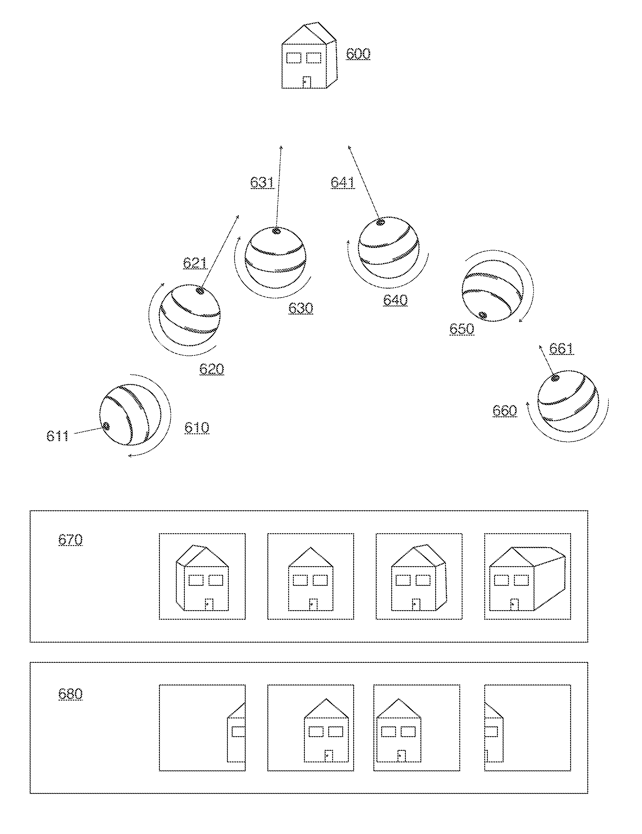
[0105]In one embodiment exampled in FIG. 5 herein and also described in parent applications, ball 520 changes shape to an egg-shape in response to aerodynamic forces acting on its surface over the course of its trajectory for the purpose of extending its range or changing direction. The exterior surface deformation trajectory changer illustrated in FIG. 5 is described in parent applications as a standalone improvement and as an improvement to a throwable camera having a trajectory trigger.

[0106]A housing that is intended to be spun into a trajectory whil...


PUM


Abstract

A camera thrown or projected into an airborne trajectory, and an image capture system with network devices collaborating for the purpose of generating panoramic images and video sourced from network cameras thrown or projected in independent trajectories, and cameras capable of capturing stable image and video from spinning, spiraling and precessing apertures, and a throwable cameras streamlined in response to aerodynamic forces acting on respective housings.

Description

CROSS-REFERENCE TO RELATED APPLICATIONS[0001]The present application is a continuation-in-part of U.S. patent application Ser. No. 13 / 492,616, Ball with camera and trajectory control for reconnaissance or recreation, filed Jun. 8, 2012, which is a continuation of U.S. patent application Ser. No. 12 / 772,198, now U.S. Pat. No. 8,237,787, Ball with camera and trajectory control for reconnaissance or recreation, filed May 1, 2010, which claims priority from U.S. Provisional Patent Application 61 / 226,618, Ball with camera and trajectory control for reconnaissance or recreation, filed Jul. 17, 2009, and also, U.S. Provisional Patent Application 61 / 177,769, Recreational Ball with Trainable Camera, filed May 13, 2009, and also, U.S. Provisional Patent Application 61 / 174,994, Recreational Ball, filed May 2, 2009. The entire contents of these applications are incorporated herein by reference.STATEMENT REGARDING FEDERALLY SPONSORED RESEARCH DEVELOPMENT[0002]Not applicable.BACKGROUND OF THE INV...

Claims


Application Information

Patent Timeline
Patent Type & Authority Applications(United States)
IPC IPC(8): H04N7/18
CPCH04N5/2252H04N7/183H04N5/23238H04N5/232H04N23/50H04N23/51H04N23/662A63B43/00H04N23/66H04N23/80
Inventor HOLLINGER, STEVEN J.
Owner HOLLINGER STEVEN J
Why Eureka
Try Eureka