System and method of establishing a multi-camera image using pixel remapping

Active Publication Date: 2013-09-26
MAGNA ELECTRONICS
View PDF34 Cites 113 Cited by
  • Summary
  • Abstract
  • Description
  • Claims
  • Application Information

AI Technical Summary

Benefits of technology

[0016]and wherein the selected pixels from the preliminary digital images are selected so that any misa

Problems solved by technology

However, such systems can require a relatively large amount of processing power to generate the image that is displ

Method used


Image

  • System and method of establishing a multi-camera image using pixel remapping
  • System and method of establishing a multi-camera image using pixel remapping
  • System and method of establishing a multi-camera image using pixel remapping

Examples


Embodiment Construction

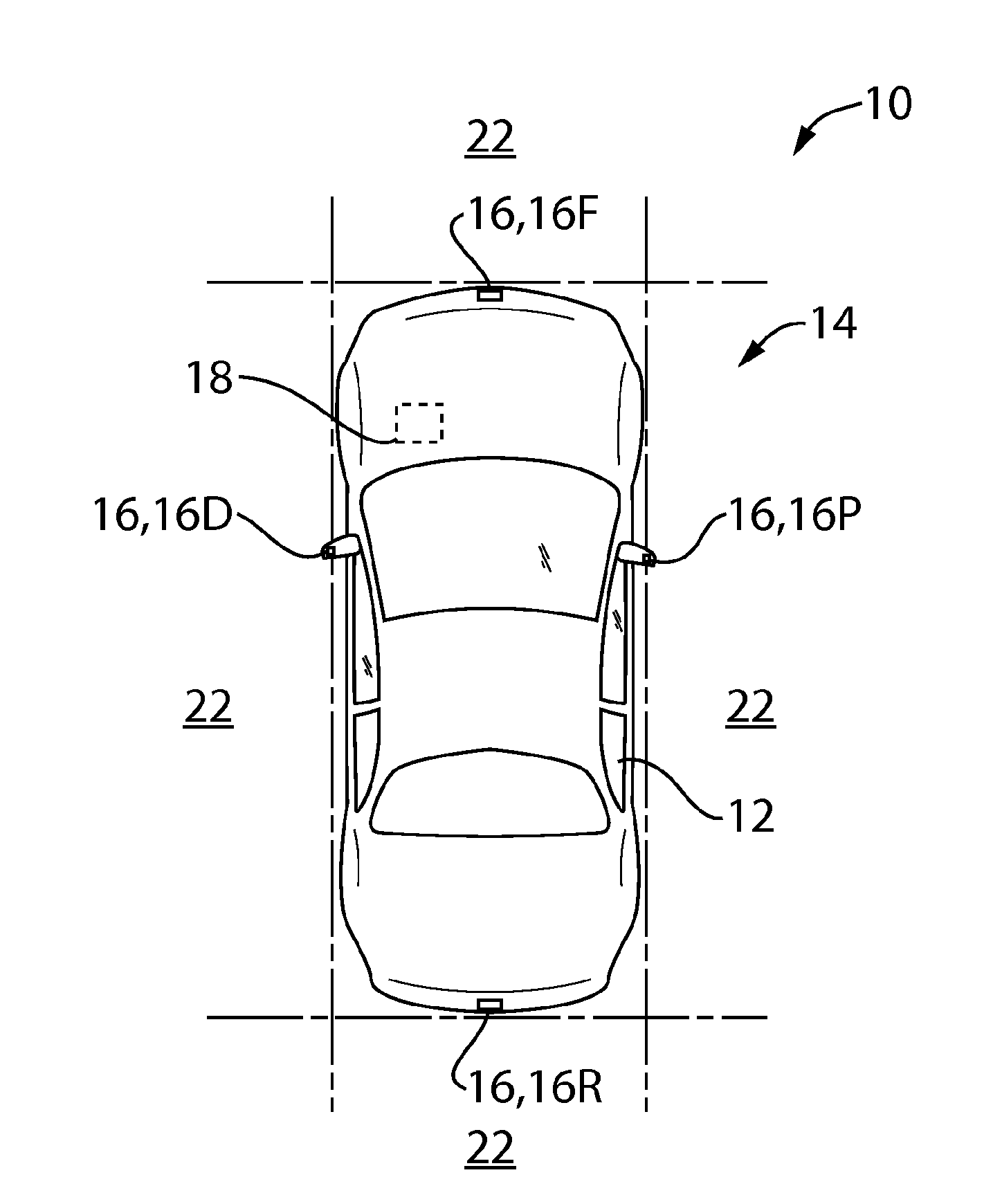
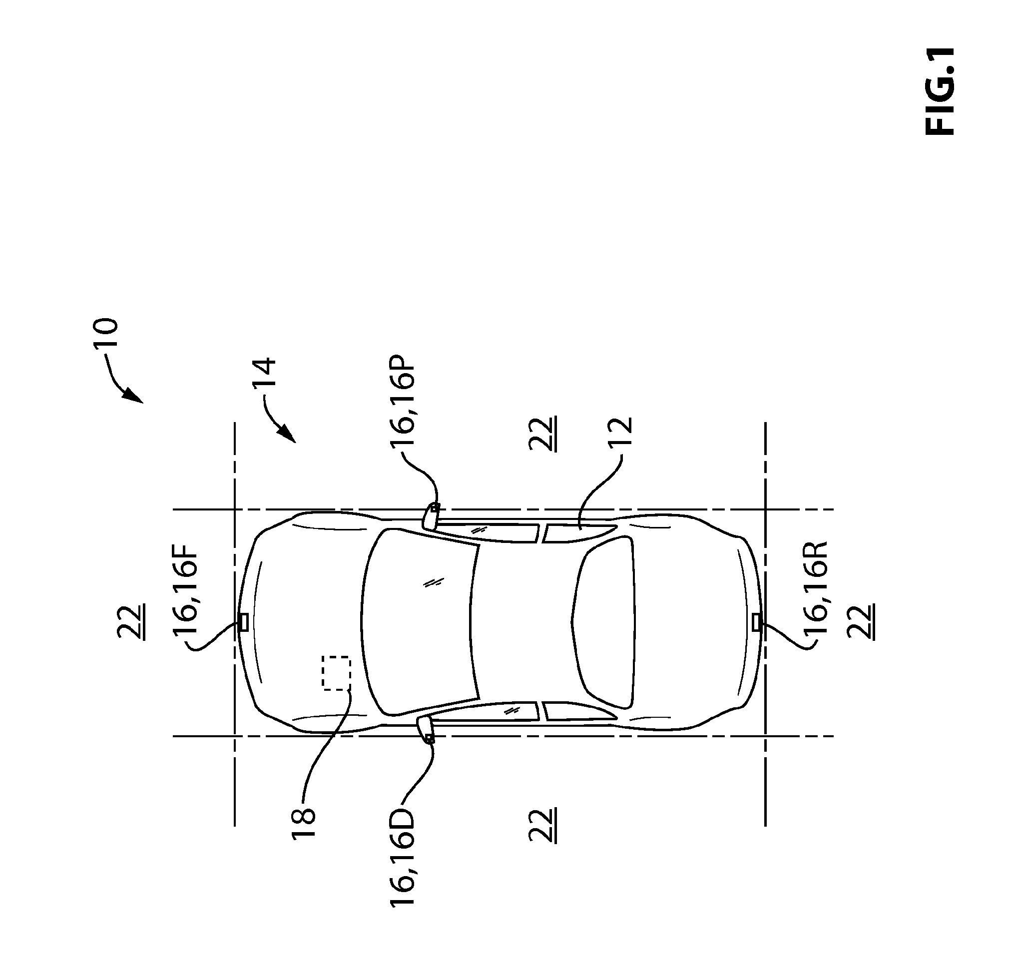
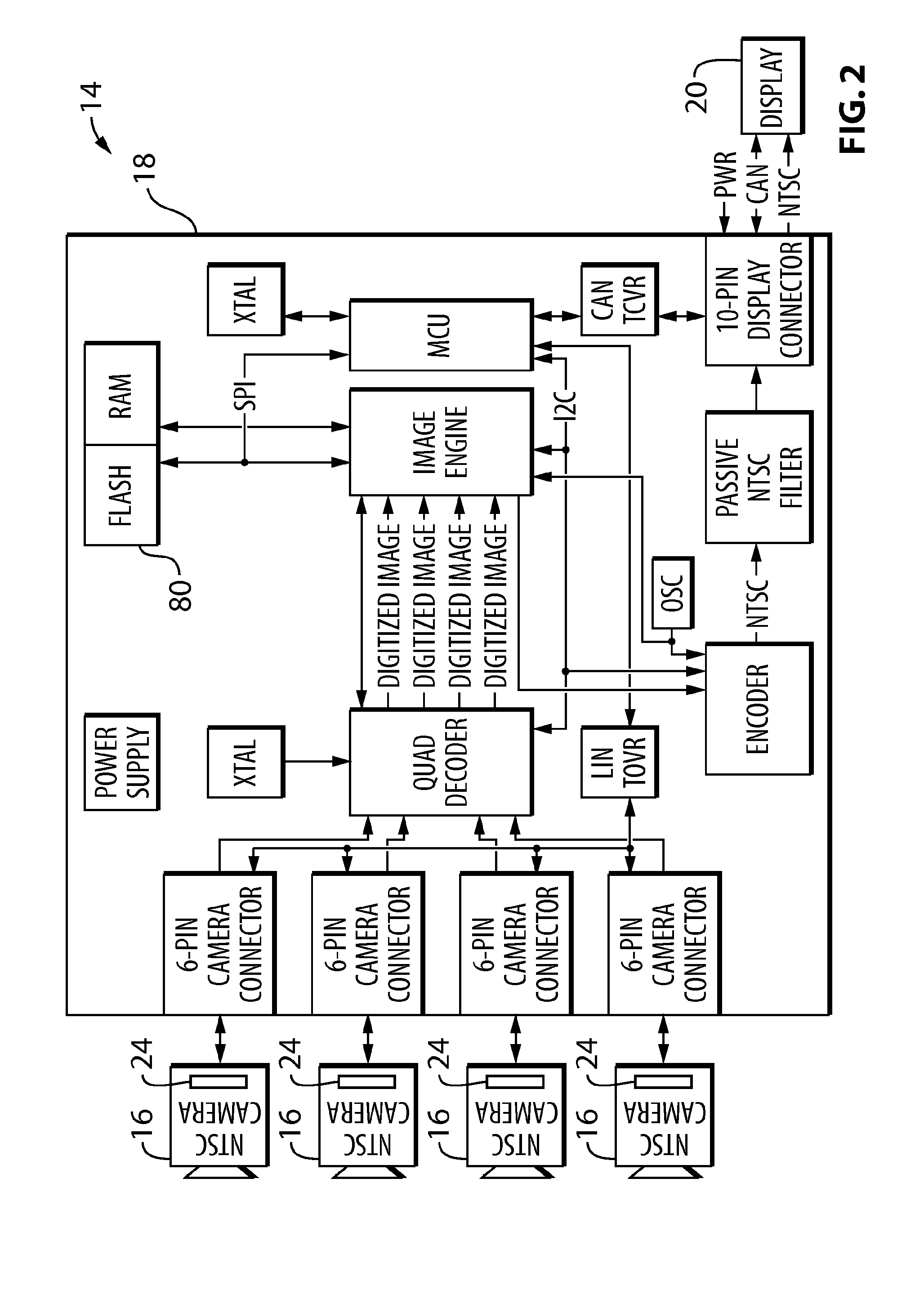
[0046]Reference is made to FIG. 1, which shows a vehicle 10 that includes a vehicle body 12, and a multi-camera system 14 in accordance with an embodiment of the present invention. The multi-camera system 14 includes four cameras 16 and a controller 18. The multi-camera system 14 is configured to display a composite image that is generated using all four cameras 16 on an in-cabin display, shown at 20 in FIG. 2. The four cameras 16 include a front camera 16F, a rear camera 16R, and driver's side and passenger side cameras 16D and 16P.

[0047]Referring to FIG. 1, each camera 16 has a field of view 22. The field of view of each camera 16 overlaps with the fields of view 22 of the two cameras 16 on either side of it. Preferably, the field of view of each camera 16 is at least about 185 degrees horizontally. Referring to FIG. 2, each camera 16 includes an image sensor 24, which is used to generate a digital image taken from the camera's field of view 22. The image sensor 24 may be any suit...


PUM


Abstract

A camera or vision system for establishing a composite image for displaying in a vehicle includes a first camera and a second camera and a controller. Each camera has a respective field of view that overlaps partially with the respective field of view of the other camera. Each camera has a respective imager for generating a respective preliminary digital image. The cameras together have a combined field of view. The controller is programmed to generate a final composite digital image that corresponds to a selected digital representation of the combined field of view of the cameras by using a remapping table to remap selected pixels from each of the preliminary digital images into selected positions of the final composite digital image. A plurality of methods for establishing a composite image are also provided.

Description

FIELD OF THE INVENTION[0001]The present invention relates to multi-camera systems for use in vehicles, and more particularly multi-camera systems for use in vehicles wherein image manipulation is carried out on the images prior to displaying the images to a vehicle occupant.BACKGROUND OF THE INVENTION[0002]There are few multi-camera systems currently available in vehicles. Such systems incorporate four cameras typically, and provide a vehicle occupant with a composite image that is generated from the images taken by the four cameras. However, such systems can require a relatively large amount of processing power to generate the image that is displayed to the vehicle occupant, particular in situations where there is manipulation of the images being carried out. Such manipulation of the images may include dewarping, among other things.[0003]It would be beneficial to provide a multi-camera system for a vehicle that requires relatively little processing power.SUMMARY OF THE INVENTION[00...

Claims


Application Information

Patent Timeline
IPC IPC(8): H04N5/262
CPCH04N5/2621H04N5/23238B60R2300/607B60R1/00B60R2300/105B60R2300/306G06T3/4038H04N23/698
Inventor LU, YUESHENG
Owner MAGNA ELECTRONICS
Why Eureka
Try Eureka