Search space for non-interleaved relay physical downlink control channel r-pdcch

a control channel and relay technology, applied in the direction of transmission path sub-channel allocation, wireless communication, wireless commuication services, etc., can solve the problems of not being able to exploit the full frequency-selective scheduling benefit of the control channel, and losing all resource assignments contained therein, etc., to achieve efficient resource utilization

Active Publication Date: 2013-09-26
SUN PATENT TRUST
View PDF3 Cites 27 Cited by
  • Summary
  • Abstract
  • Description
  • Claims
  • Application Information

AI Technical Summary

Benefits of technology

[0068]Advantageously, the positions of distributed candidates with the second number of aggregated control channel elements for a first receiving node are different to positions of distributed candidates with the second number of aggregated control channel elements for a second receiving node. This enables an efficient mapping without blocking the resources for the receiving-node-dedicated signalling.
[0069]According to an embodiment of the present invention, candidates with a higher number of aggregated control channel elements localised on adjacent frequencies are located in frequency without overlapping with candidates with a lower number of aggregated control channel elements. Such an arrangement is particularly advantageous since it enables efficient utilization of resources without blocking. This means, for instance, that assignment of level 1 candidates does not block assignment of a level 2 candidate but rather, both may be assigned to the same or different receiving nodes.

Problems solved by technology

If the user equipment (UE) is unable to decode the PCFICH or if it obtains an erroneous PCFICH value, it will not be able to correctly decode the L1 / L2 control signalling (PDCCH) comprised in the control signalling region, which may result in losing all resource assignments contained therein.
This would, in turn, make it impossible to exploit the full frequency-selective scheduling benefit for the control channel.

Method used


Image

  • Search space for non-interleaved relay physical downlink control channel r-pdcch
  • Search space for non-interleaved relay physical downlink control channel r-pdcch
  • Search space for non-interleaved relay physical downlink control channel r-pdcch

Examples


Embodiment Construction

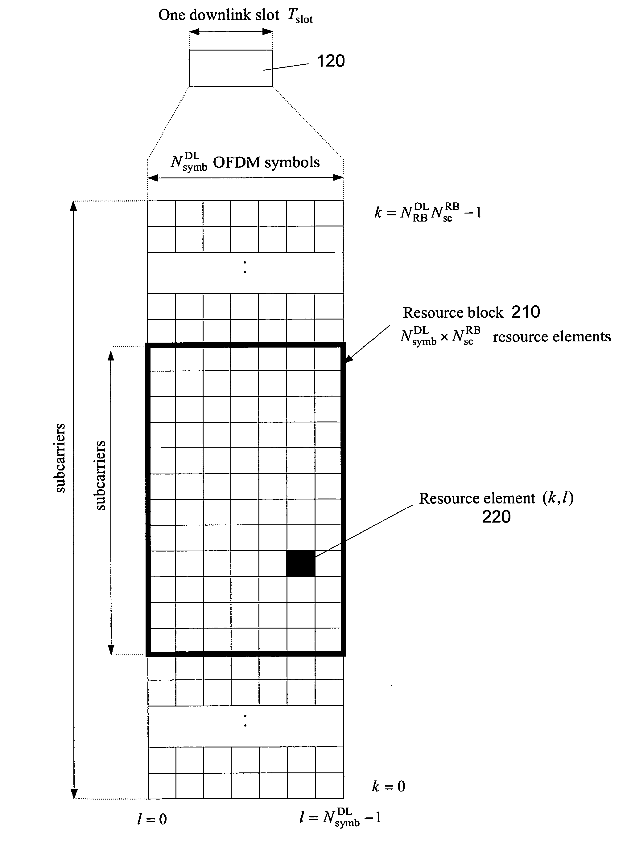
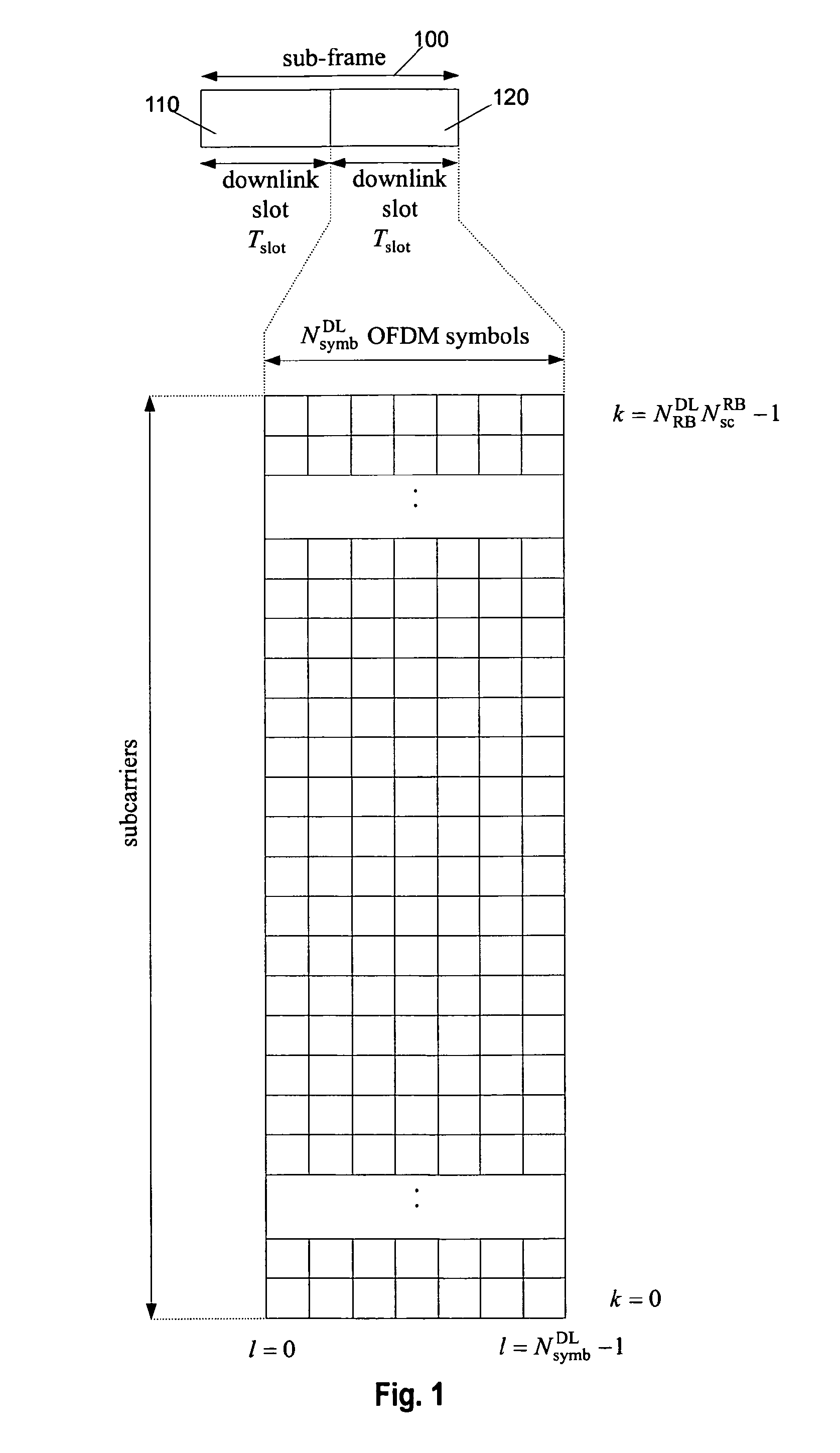
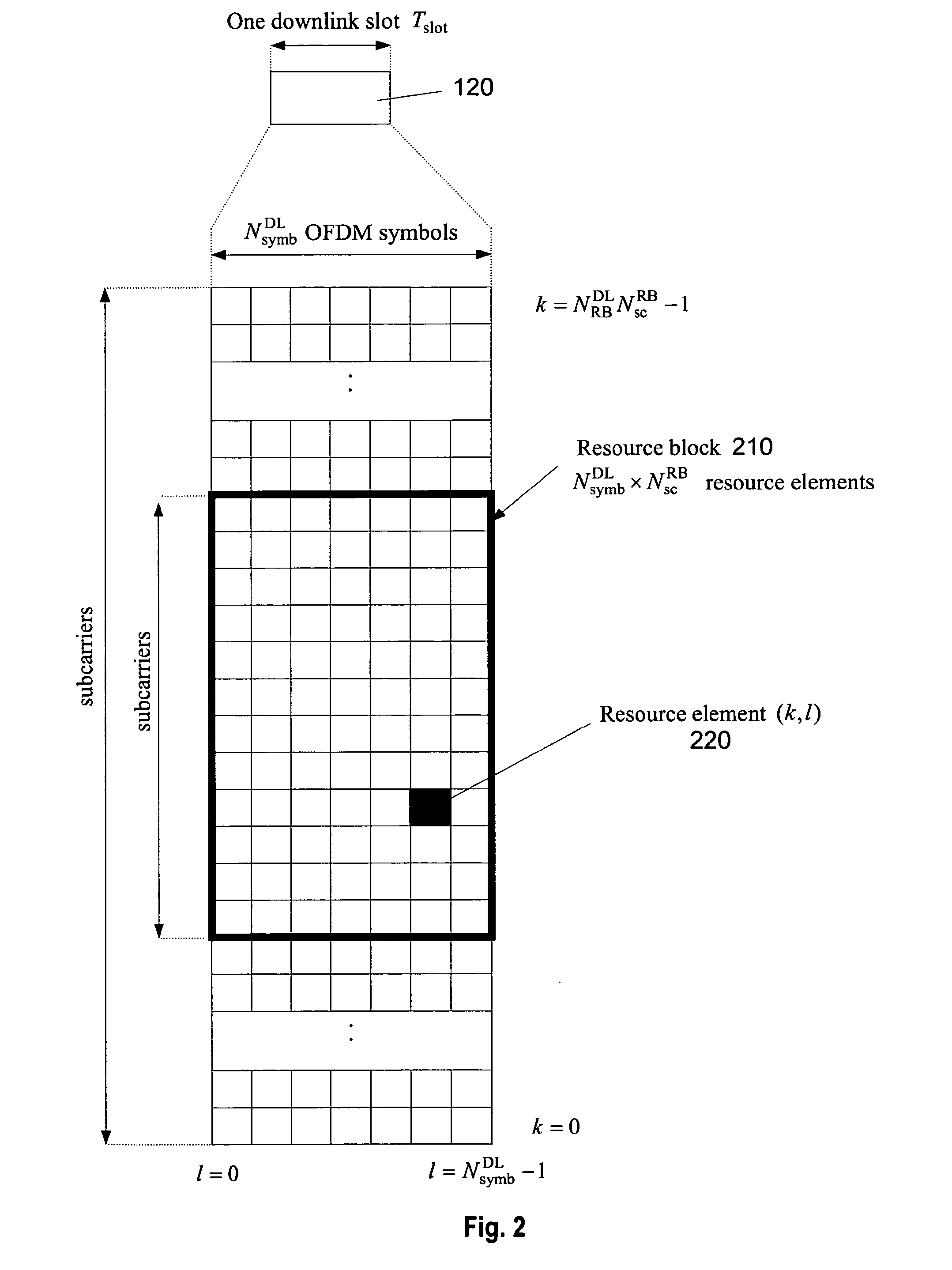
[0091]The following paragraphs will describe various embodiments of the present invention. For exemplary purposes only, most of the embodiments are outlined in relation to an OFDM downlink radio access scheme according to 3GPP LTE (Release 8) and LTE-A (Release 10) mobile communication systems discussed in the Technical Background section above. It should be noted that the invention may be advantageously used for example in connection with a mobile communication system such as 3GPP LTE (Release 8) and LTE-A (Release 10) communication systems previously described, but the invention is not limited to its use in this particular exemplary communication network. The aspects of the invention described herein may be inter alia used for defining the search spaces for uplink and downlink control information (R-PDCCH), mainly carrying assignments and grants for receivers such as relay nodes or UEs in a 3GPP LTE-A (Release 10) communication systems and for providing an effective resource utili...


PUM


Abstract

The present invention relates to providing control information within a search space for blind decoding in a multi-carrier communication system. In particular, the control information is carried within a sub-frame of the communication system, the sub-frame including a plurality of control channel elements. The control channel elements may be aggregated into candidates for blind decoding. The number of control channel elements in a candidate is called aggregation level. In accordance with the present invention, the candidates of lower aggregation levels are localised, meaning that the control channel elements of one candidate are located adjacently to each other in the frequency domain. Some candidates of the higher aggregation level(s) are distributed in the frequency.

Description

FIELD OF THE INVENTION[0001]The present invention relates to signalling uplink and downlink grant in an OFDM-based mobile communication system. In particular, the present invention relates to methods and apparatuses for configuration of search space and to search space channel structure for signalling of the uplink and downlink grant control information.BACKGROUND OF THE INVENTION[0002]Third generation (3G) mobile systems, such as, for instance, universal mobile telecommunication systems (UMTS) standardized within the third generation partnership project (3GPP) have been based on wideband code division multiple access (WCDMA) radio access technology. Today, 3G systems are being deployed on a broad scale all around the world. After enhancing this technology by introducing high-speed downlink packet access (HSDPA) and an enhanced uplink, also referred to as high-speed uplink packet access (HSUPA), the next major step in evolution of the UMTS standard has brought the combination of ort...

Claims


Application Information

Patent Timeline
Patent Type & Authority Applications(United States)
IPC IPC(8): H04W72/04
CPCH04L1/0038H04L1/0046H04L1/009H04L1/0091H04W72/042H04L5/0053H04L27/261H04L2001/0097H04L5/0037H04W72/23H04W72/0453
Inventor GOLITSCHEK EDLER VON ELBWART, ALEXANDERFENG, SUJUANWENGERTER, CHRISTIANSUZUKI, HIDETOSHI
Owner SUN PATENT TRUST
Why Eureka
Try Eureka