Electrical connector having position fixer for conductive terminals

Active Publication Date: 2013-09-26
HON HAI PRECISION IND CO LTD
View PDF5 Cites 1 Cited by
  • Summary
  • Abstract
  • Description
  • Claims
  • Application Information

AI Technical Summary

Benefits of technology

[0008]Accordingly, an object of the present invention is to maintain a positional relationship between a plurality of conducti

Problems solved by technology

Because of the electrical connector has a large number conductive terminals, it is not easy to lead all of the conductive terminals solder into the printed circuit board accurately.
Therefore, when the electrical c

Method used


Image

  • Electrical connector having position fixer for conductive terminals
  • Electrical connector having position fixer for conductive terminals
  • Electrical connector having position fixer for conductive terminals

Examples


Embodiment Construction

[0023]Reference will now be made in detail to the preferred embodiment of the present invention.

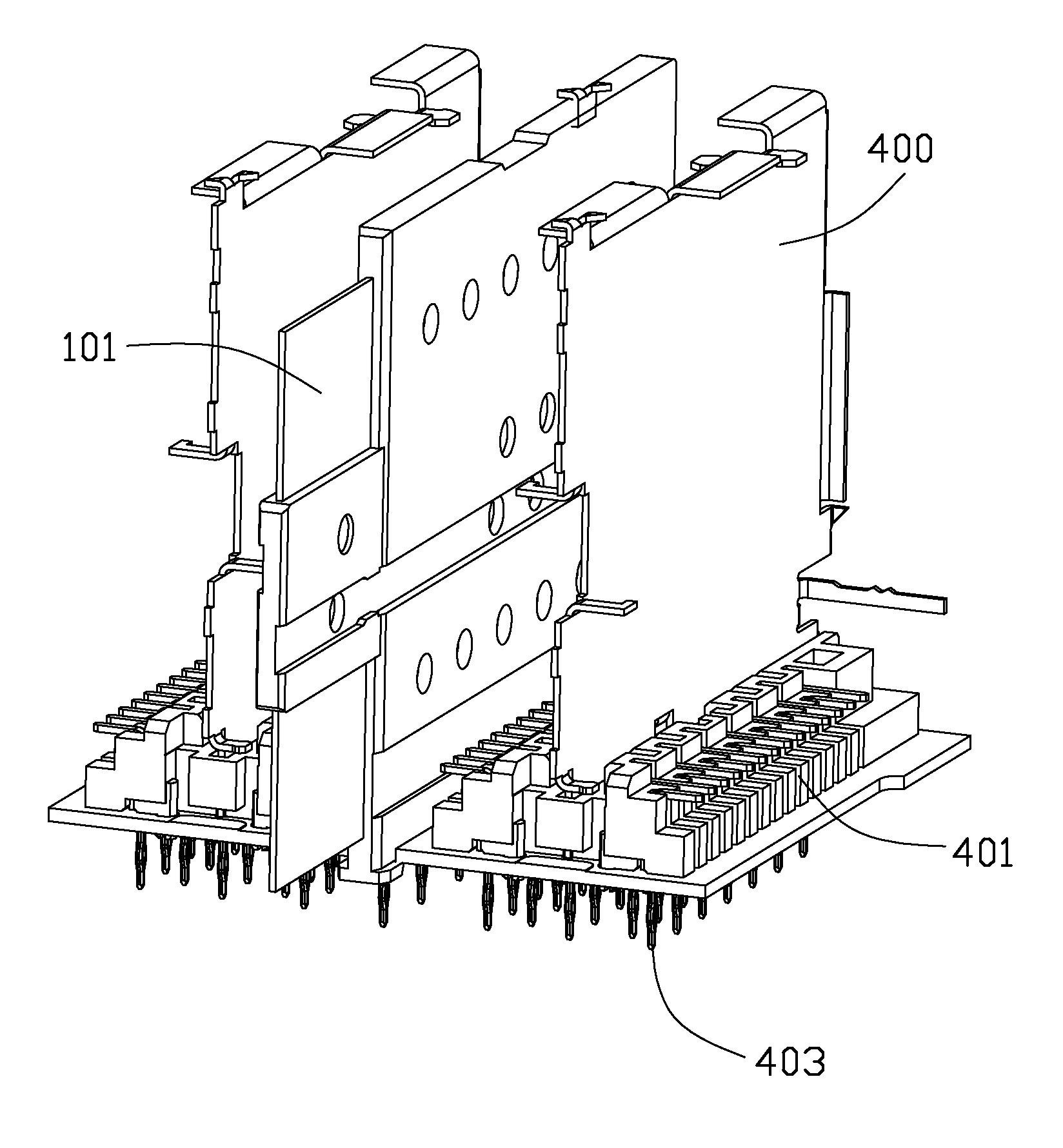
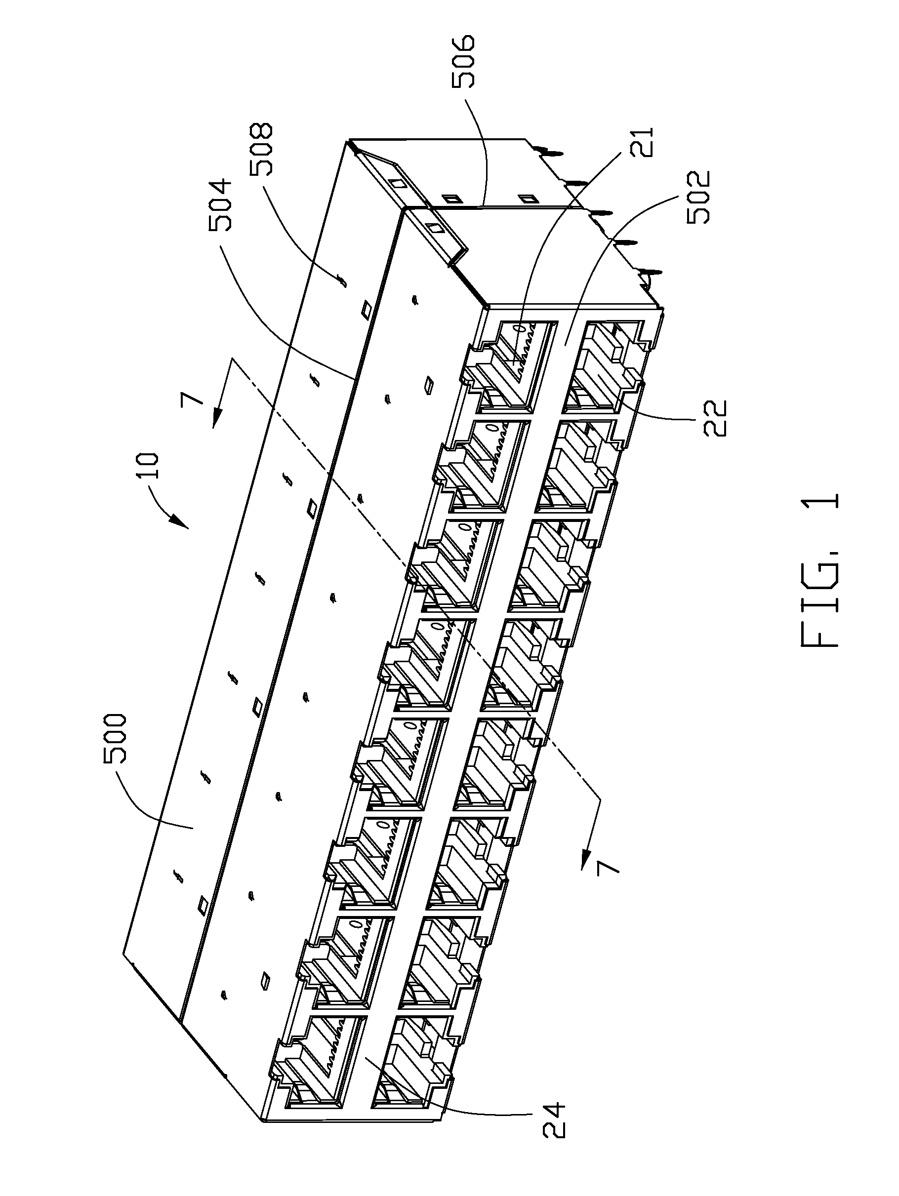
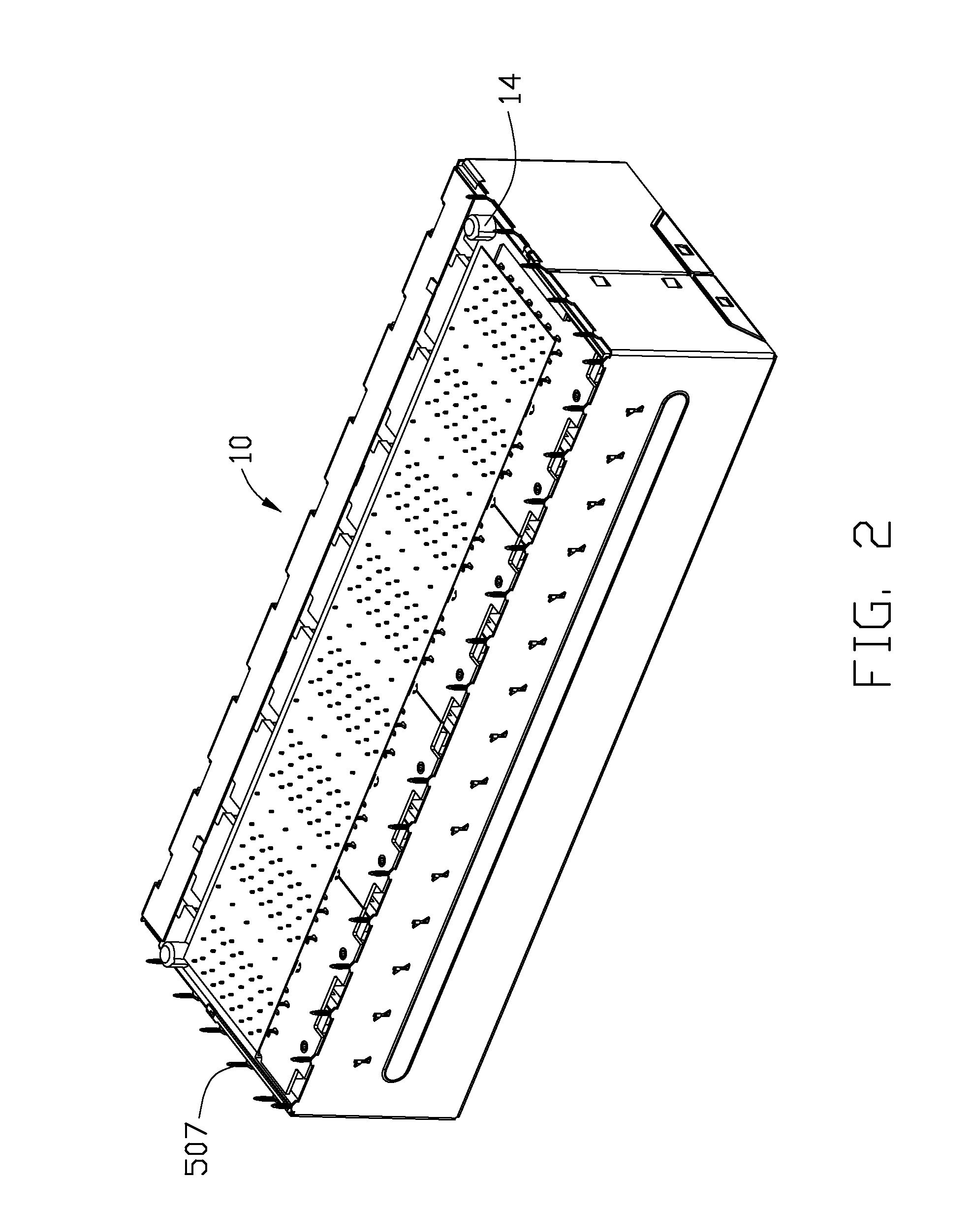
[0024]Referring to FIGS. 1 to 8, there is shown a 2×8-port electrical connector or modular jack 10 adapted for being mounted onto a printed circuit board (not shown) defining a plurality of vias (not shown). The electrical connector 10 has a row of upper ports 21 and a row of lower ports 22 vertically stacked in columns. Both of the upper and lower ports 21, 22 are used to receive a modular plug (not shown) with a high speed up to 10 Gigabit / second. One modular plug inserts into either the upper or the lower port 21 or 22 along an insertion direction. The electrical connector 10 includes an insulative housing 200, a plurality of contact modules 400 received in the insulative housing 200, a plurality of sub-circuit boards 600 used for reducing signal interference and a shielding shell 500 enclosing the insulative housing 200. The contact module 400 further comprises contacts, inner printed...


PUM


Abstract

An electrical connector (10) adapted for being mounted onto a printed circuit board (PCB) including a number of vias. The electrical connector includes an insulative housing (200) having a board mounting surface (12), a contact module (400) assembled to the insulating housing (200) and including a number of conductive terminals (403), and a positioning fixer (300) mounting to the conductive terminals. Each of the conductive terminals includes a pin end extending beyond the mounting surface for being inserted into one of the PCB vias. The position fixer (300) has a plurality of through holes (301) each retaining to a corresponding pin end (405) prior to the position fixer (300) being moved up to the mounting surface when the electrical connector is mounted to the PCB.

Description

BACKGROUND OF THE INVENTION[0001]1. Field of the invention[0002]The present invention relates to an electrical connector and method of making the same, and more particularly to an electrical connector suitable for high-speed communication.[0003]2. Description of Related Art[0004]Chinese Patent No. 201498790 issued on Jun. 2, 2010 discloses a related art. According to the disclosure, an electrical connector adapted for being mounted onto a printed circuit boards includes an insulative housing and a plurality of conductive terminals received in the insulative housing. The insulative housing has a mounting surface. The conductive terminals extend through the mounting surface to solder on the printed circuit board. Because of the electrical connector has a large number conductive terminals, it is not easy to lead all of the conductive terminals solder into the printed circuit board accurately.[0005]U.S. Pat. No. 6,840,817 issued on Jan. 11, 2005 and U.S. Pat. No. 6,585,540 issued on Jul...

Claims


Application Information

Patent Timeline
IPC IPC(8): H01R12/51H05K3/00
CPCY10T29/49147H05K3/00H01R43/0256H05K3/308H05K2203/167H01R12/724H05K2201/10189H01R13/6587H01R43/0263H01R12/51
Inventor ZHANG, ZHI-CHENG
Owner HON HAI PRECISION IND CO LTD
Why Eureka
Try Eureka