Waste receptacle with improved venting system and deodorizing system

a waste receptacle and venting system technology, applied in the field of pressure differential relief waste receptacles, can solve the problems of attracting bugs and microorganisms, smelling like garbage in the entire area,

Inactive Publication Date: 2013-09-26
SMITH JOHN G
View PDF1 Cites 18 Cited by
  • Summary
  • Abstract
  • Description
  • Claims
  • Application Information

AI Technical Summary

Benefits of technology

[0014]In another embodiment, the invention provides a cartridge for use in a vented trash receptacle, the cartridge comprising: an outer surface at least in part configured to be received into a vacuum relief component of a trash receptacle; an intake adapted to receive ambient air drawn into the vacuum relief component of the receptacle; an output adapted to output t

Problems solved by technology

Odor, mold, bacteria and under undesirable conditions often build up as the waste receptacle is used over time, and can be especially troublesome in outdoor waste receptacles or large commercial or industrial receptacles where the garbage sits for periods of time.

Method used


Image

  • Waste receptacle with improved venting system and deodorizing system
  • Waste receptacle with improved venting system and deodorizing system
  • Waste receptacle with improved venting system and deodorizing system

Examples


second embodiment

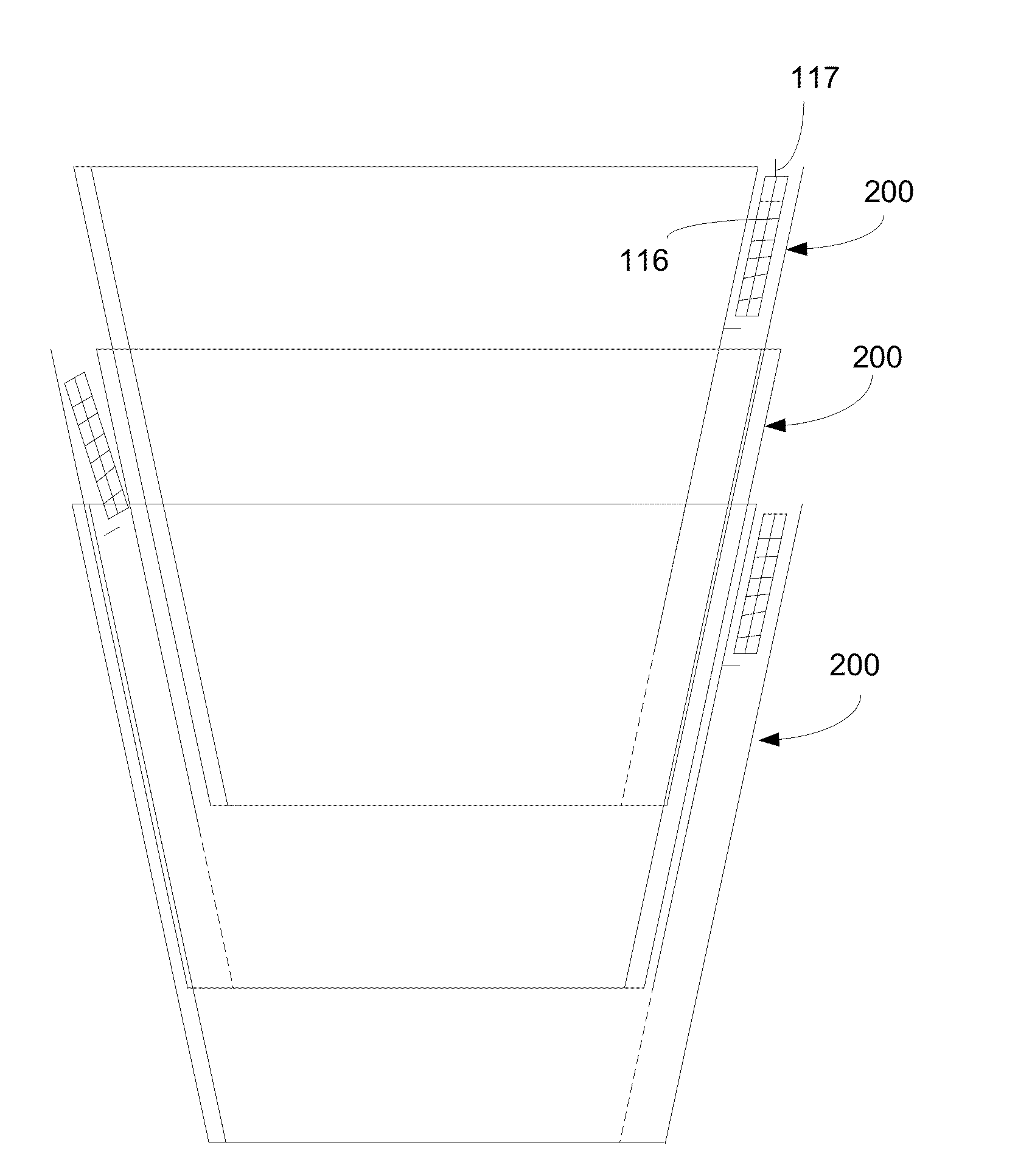
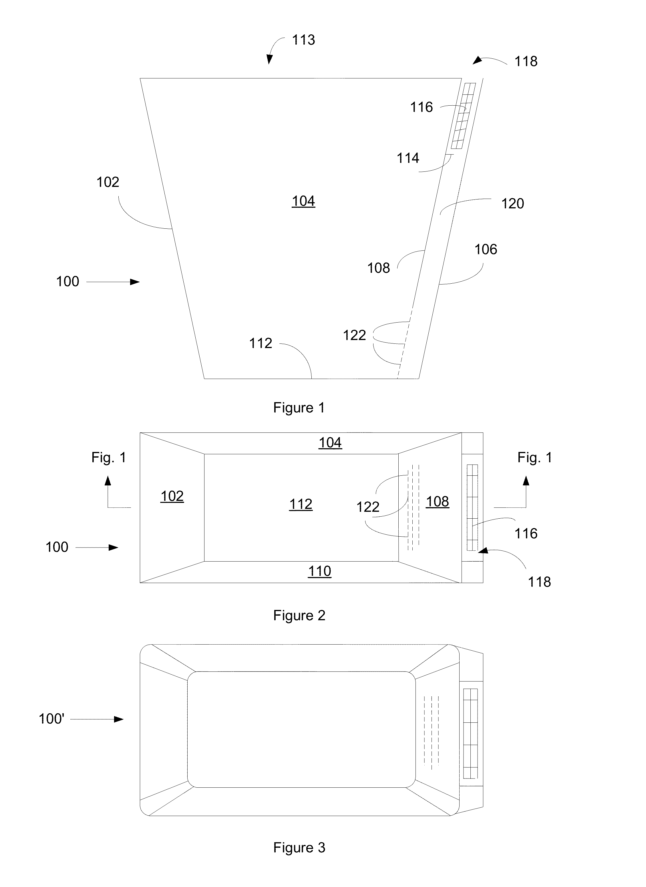
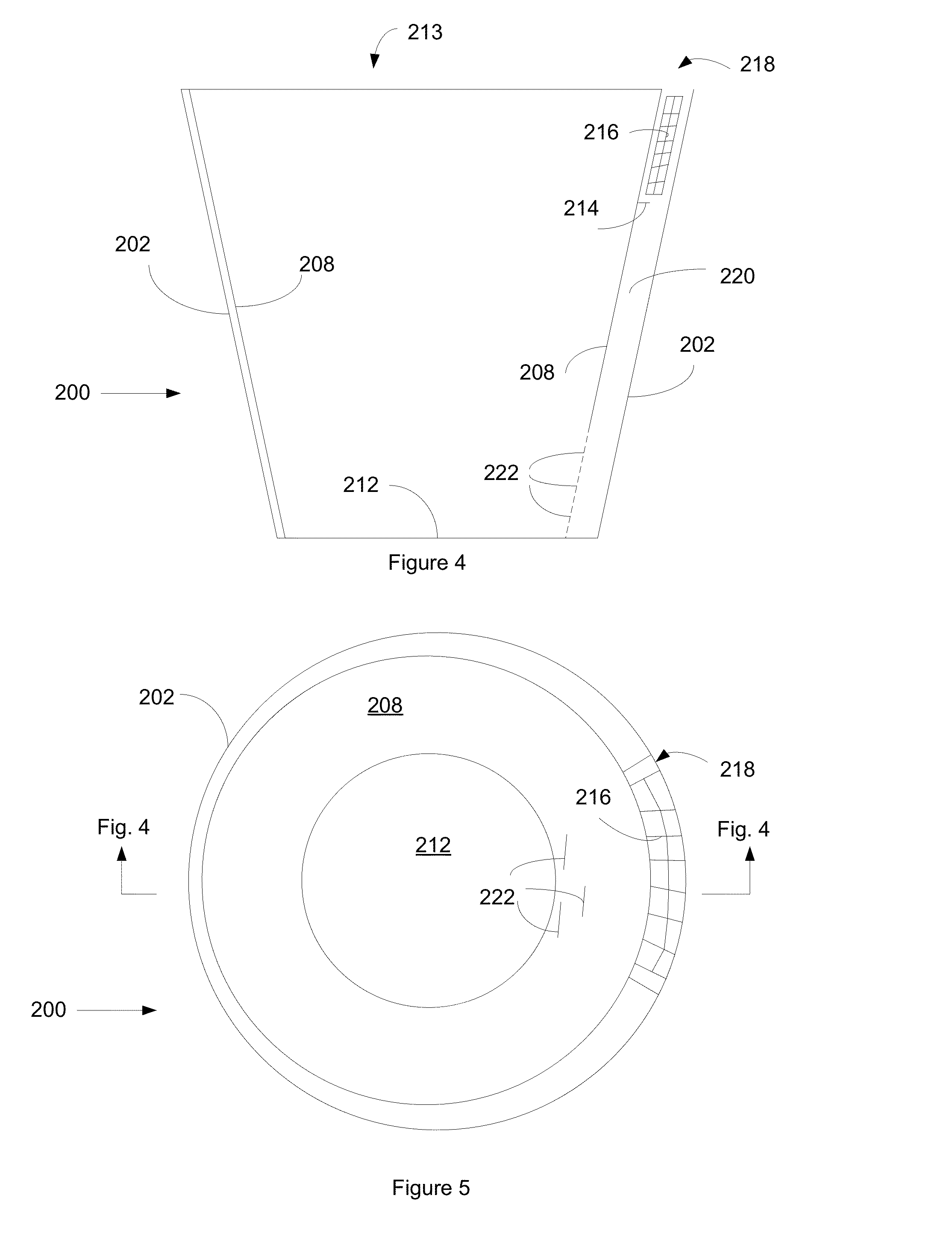
[0035]FIG. 4 shows a front cross-section of the present invention. This embodiment shows a slightly tapered cylindrical waste receptacle 200 with a sidewall 202, a bottom 212, which is connected to the side wall 202, and an open top 213. The cylindrical waste receptacle 200 can be either double walled, or single walled. If the receptacle 200 is double walled, there is an inner sidewall 208. If receptacle 200 is single walled, 208 refers to the inside of the outer sidewall. There is an air conduit 220, which runs the height of the waste receptacle 200. At the top of the air conduit 220, there is an intake opening 218, and at the bottom of the air conduit there is / are exhaust opening(s) 222 into the waste receptacle 200. Near the top of the conduit 200, there is a shelf 214 that extends part of the way into the air conduit, and which supports the deodorizing media 216 while in the air conduit. The operation of the receptacle is as described above in the context of FIG. 1 and multiple ...

third embodiment

[0037]FIG. 6 shows a front cross-section of the present invention. This embodiment shows a slightly tapered cylindrical waste receptacle 300 with an outer sidewall 306, and an inner sidewall 308, which form the air conduit 320. The intake opening 318 of the air conduit 320 is located near the middle of the waste receptacle 300. Just below the intake opening 318 on the outer sidewall 306 of the waste receptacle 300 is a hinged flap 324. The hinged flap 324 has a closed position 324 and an open position 324′. When the hinged flap is in the open position 324′ the deodorizing media 316 is placed in the air conduit and rests on the shelf 314 which extends from the outer sidewall into the air conduit. The flap may include a ledge or shelf to support the cartridge or may include a pocket or other means for receiving loose deodorizing agents. Near the bottom of the air conduit 320, are the exhaust openings 322.

fourth embodiment

[0038]FIG. 7 shows a lower portion of an alternative configuration in cross-section of a waste receptacle 400. This fourth embodiment shows an air conduit 420 which has an intake opening 418 near the bottom of the receptacle 400. Immediately below the intake opening 418 on the outer sidewall of the waste receptacle 400 is a hinged flap 424. The hinged flap 424 has a closed position 424 and an open position 424′. When the hinged flap is in the open position 424′ the deodorizing media 416 is placed in the air conduit and rests on the bottom of the air conduit 420, which is at the bottom of the sidewall of the receptacle 400. Opposite the hinged flap 424, are the exhaust openings 422.

[0039]FIG. 8 shows yet another alternative embodiment of a receptacle 500 having a compartment 524 for receiving deodorizing media 516 and having intake opening(s) 518 located on the bottom wall 512 of the receptacle and exhaust opening(s) 522 located on the top of compartment 524. The compartment 524 may ...


PUM

PropertyMeasurementUnit
Pressureaaaaaaaaaa
Sizeaaaaaaaaaa
Adhesivityaaaaaaaaaa

Abstract

The present invention relates to a deodorizing system for a waste receptacle with a venting system. More particularly, the present invention relates to a waste receptacle that contains a venting system which allows air to enter the receptacle when removing a trash liner, thus allowing the liner to be removed more easily than before. Additionally, as the air moves through the venting system and across or through a deodorizing media, a fresh scent, anti-bacterial agent or other desired effect is provided when the garbage liner is removed from the waste receptacle.

Description

CROSS-REFERENCE TO RELATED APPLICATION[0001]This application claims the benefit of U.S. Provisional Patent Application No. 61 / 192,419, filed Sep. 18, 2008, and U.S. Ser. No. 12 / 586,206, filed Sep. 18, 2009, entitled WASTE RECEPTACLE WITH IMPROVED VENTING SYSTEM AND DEODORIZING SYSTEM, both of which are incorporated by reference herein.BACKGROUND OF THE INVENTION[0002](a) Field of the Invention[0003]The present invention relates to waste receptacles and other containers or objects that receive and support liners, such as trash bags. More particularly, the invention relates to a pressure differential relief waste receptacle that is arranged to prevent pressure differential adherence of a waste receptacle liner to the waste receptacle during removal of the liner.[0004](b) Background of the Invention[0005]Trash receptacles are a common household item often found in several areas of the home. Trash liners are inserted in trash receptacles and are typically plastic and conform and adhere ...

Claims


Application Information

Patent Timeline
IPC IPC(8): F24F7/00A61L9/00
CPCF24F2003/1664F24F2003/1689B65F2220/12B65F2210/129B65F1/068F24F8/20F24F8/50
Inventor SMITH, JOHN G.
Owner SMITH JOHN G
Why Eureka
Try Eureka