
Control apparatus for hybrid vehicle

a control apparatus and hybrid technology, applied in the direction of automatic control systems, process and machine control, instruments, etc., can solve the problems of dissatisfaction with the actual output characteristics of the vehicle, and achieve the effects of high degree of efficiency, high degree of drivability of the hybrid vehicle, and risk of deterioration of the fuel economy of the vehicl

Active Publication Date: 2013-09-26
TOYOTA JIDOSHA KK
View PDF9 Cites 33 Cited by
  • Summary
  • Abstract
  • Description
  • Claims
  • Application Information

AI Technical Summary

Benefits of technology

This patent describes a control system for a hybrid vehicle that can change the output characteristics of the vehicle based on the operating state of the vehicle. This allows for better control and efficiency of the vehicle's engine and electric motor. The control system can selectively establish a first drive state where the electric motor is the main driver, a second drive state where the electric motor and engine work together, and a third drive state where the electric motor is the main driver. The output characteristic is set so that the vehicle drive force is larger in the second and third drive states than in the first state, even if the electric energy storage device has limited capacity. This ensures that the vehicle can still provide the necessary power for starting the engine, and that the engine operates with high efficiency in all driving modes. The control system can also selectively establish different drive modes based on the operator's preferences, and the output characteristic is changed accordingly to provide better control and efficiency in each mode.

Problems solved by technology

Therefore, the vehicle operator expecting the sporty running of the vehicle as a result of starting of the engine may be dissatisfied with the actual output characteristics of the vehicle which are identical with those in the drive state in which the vehicle drive force is generated by only the electric motor.

Method used


Image

  • Control apparatus for hybrid vehicle
  • Control apparatus for hybrid vehicle
  • Control apparatus for hybrid vehicle

Examples


embodiments

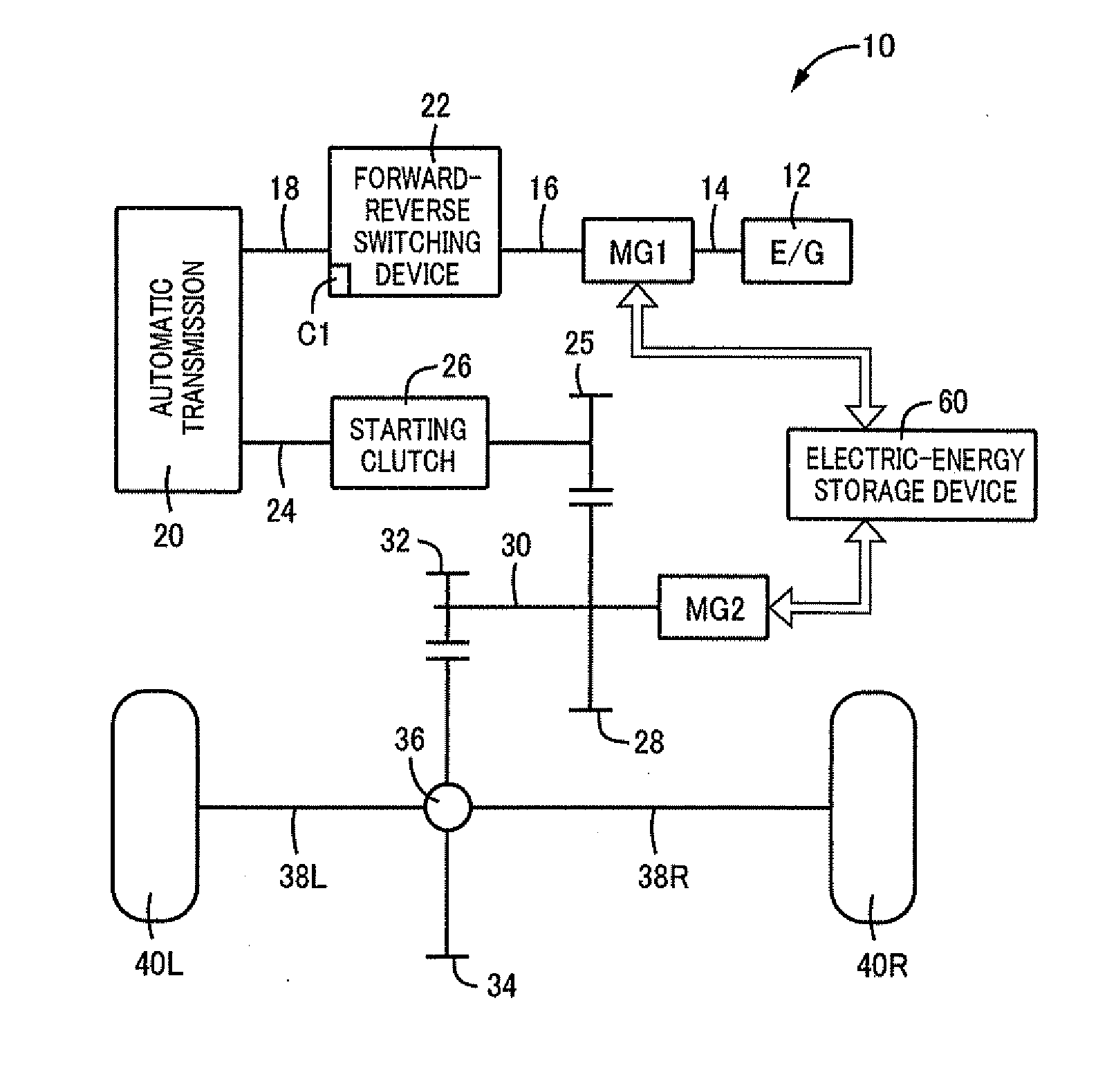
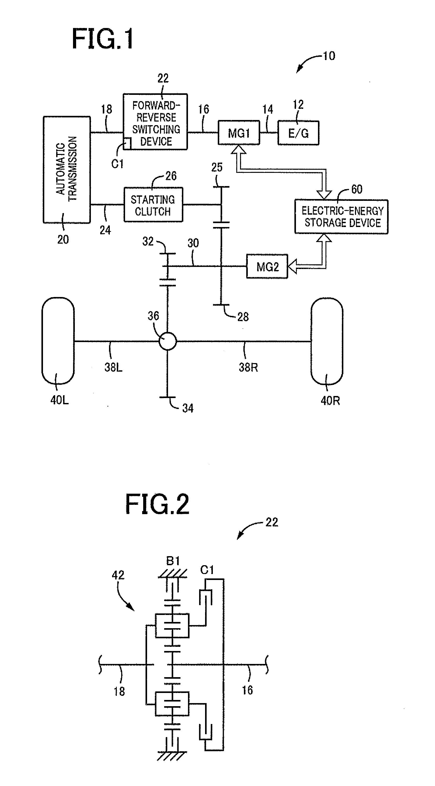
[0031]FIG. 1 is the schematic view shown the arrangement of a drive system provided on a hybrid vehicle 10 to which the present invention is suitably applicable. As shown in FIG. 1, the hybrid vehicle 10 according to the present invention is provided with: an engine 12; a first motor / generator MG1 connected to a crankshaft 14 of the engine 12; a forward-reverse switching device 22 connected to the first motor / generator MG1 through an intermediate shaft 16 and to an automatic transmission 20 through an input shaft 18; a starting clutch 26 interposed between an output shaft 24 of the automatic transmission 20 and a first gear 25 and configured to selectively place a power transmitting path therebetween in a power transmitting state and a power cut-off state; a counter shaft 30 on which a second gear 28 meshing with the first gear 25 is mounted; a second motor / generator MG2 connected to the counter shaft 30; a third gear 32 mounted on the counter shaft 30; a differential gear device 36...


PUM


Abstract

A vehicle control apparatus configured to selectively establish one of a first drive state in which a vehicle drive force is generated primarily by a second motor / generator operated with an electric energy supplied from an electric-energy storage device while an engine is placed in a rest state, and a second drive state in which a first motor / generator is operated with a drive force of the engine, to generate an electric energy and in which the vehicle drive force is generated primarily by the second motor / generator operated with at least the electric energy generated by the first motor / generator. The vehicle control apparatus is further configured such that the vehicle drive force generated in the second drive state at a given value of an accelerator pedal operation amount θacc is larger than that generated in the first drive state.

Description

TECHNICAL FIELD[0001]The present invention relates to a control apparatus for a hybrid vehicle, and more particularly to an improvement of the control apparatus, which permits a higher degree of drivability of the hybrid vehicle depending upon whether an engine is in an operated state or not.BACKGROUND ART[0002]There is known a hybrid vehicle provided with an engine, a first electric motor connected to the engine, a second electric motor connected to wheels, and an electric-energy storage device for supplying an electric energy to the above-indicated first and second electric motors. For such a hybrid vehicle, there has been proposed a control technique for changing output characteristics of a vehicle drive force corresponding to an operation amount of an accelerator pedal, depending upon a running state of the hybrid vehicle. Patent Document 1 discloses an example of a control apparatus for the hybrid vehicle. This control apparatus is configured to selectively establish one of a f...

Claims


Application Information

Patent Timeline
Patent Type & Authority Applications(United States)
IPC IPC(8): B60W20/00B60W10/08B60W10/02B60W10/06B60L50/16
CPCB60W10/02B60W10/06B60W10/08B60W20/20B60W2600/00Y10S903/93B60W20/40B60W50/082B60W20/00Y02T10/6239B60W50/10B60W2540/10B60K6/445B60K6/442Y02T10/62B60W2556/00B60W2540/215B60W20/10B60W30/182
Inventor MARUYAMA, TOMOYUKIMIYAGAWA, TAKESHIFURUKAWA, TOMOAKIII, RYOKISATO, AKIHIROYAMAMURA, NORIHIRONISHIMINE, AKIKOKANAYAMA, TAKESHIHORI, TETSUOHAYASHI, KOJI
Owner TOYOTA JIDOSHA KK
Learn More