Method for manufacturing sealed cell

a cell and sealing technology, applied in the direction of cell components, conductors, cell component details, etc., can solve the problems of reducing cell performance, generating spatters, cracks in the welding spot, etc., and achieve the effect of excellent sealing properties and high ruggedness

Inactive Publication Date: 2013-10-03
SANYO ELECTRIC CO LTD
View PDF2 Cites 3 Cited by
  • Summary
  • Abstract
  • Description
  • Claims
  • Application Information

AI Technical Summary

Benefits of technology

[0037]As described above, the method of the present invention can effectively prevent the generation of holes or undercuts in the melted-solidified region 6, which is the result of the sealing body 2 being welded to the outer can 1, thereby providing a sealed cell with excellent sealing property and high ruggedness.

Problems solved by technology

In this method, insufficient weld strength may cause cracks in the welded spot when the cell is dropped or subjected to other impact.
The cracks may cause leakage of the electrolytic solution, and entry of oxygen or moisture into the cell, thereby reducing cell performance.
This approach, however, leads to generation of spatters and early deterioration of laser devices.
Laser welding, however, has the following problem.
As a result, as shown in FIG. 8B, undercuts 5 are generated in a melting section 3, thereby causing the weld strength to be insufficient.
The presence of these holes causes the weld strength to be insufficient.

Method used


Image

  • Method for manufacturing sealed cell
  • Method for manufacturing sealed cell
  • Method for manufacturing sealed cell

Examples


Embodiment Construction

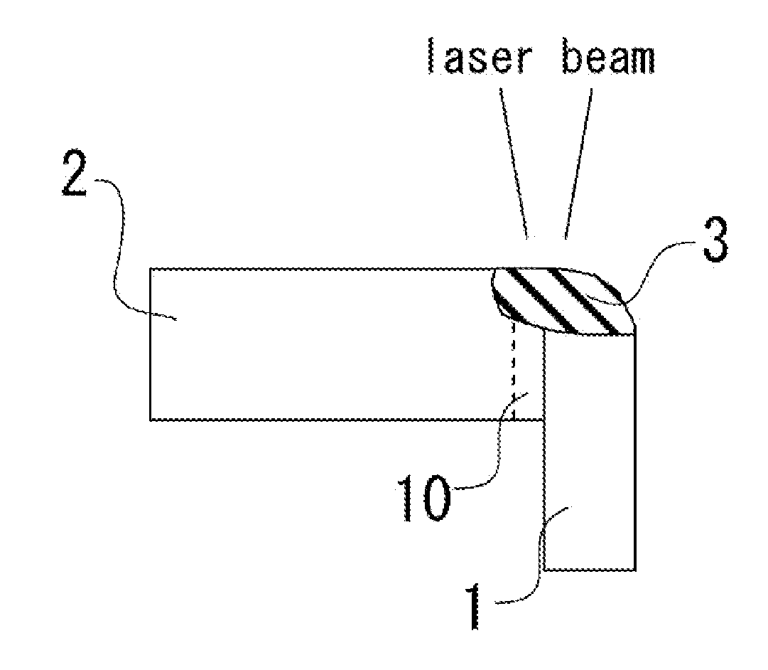
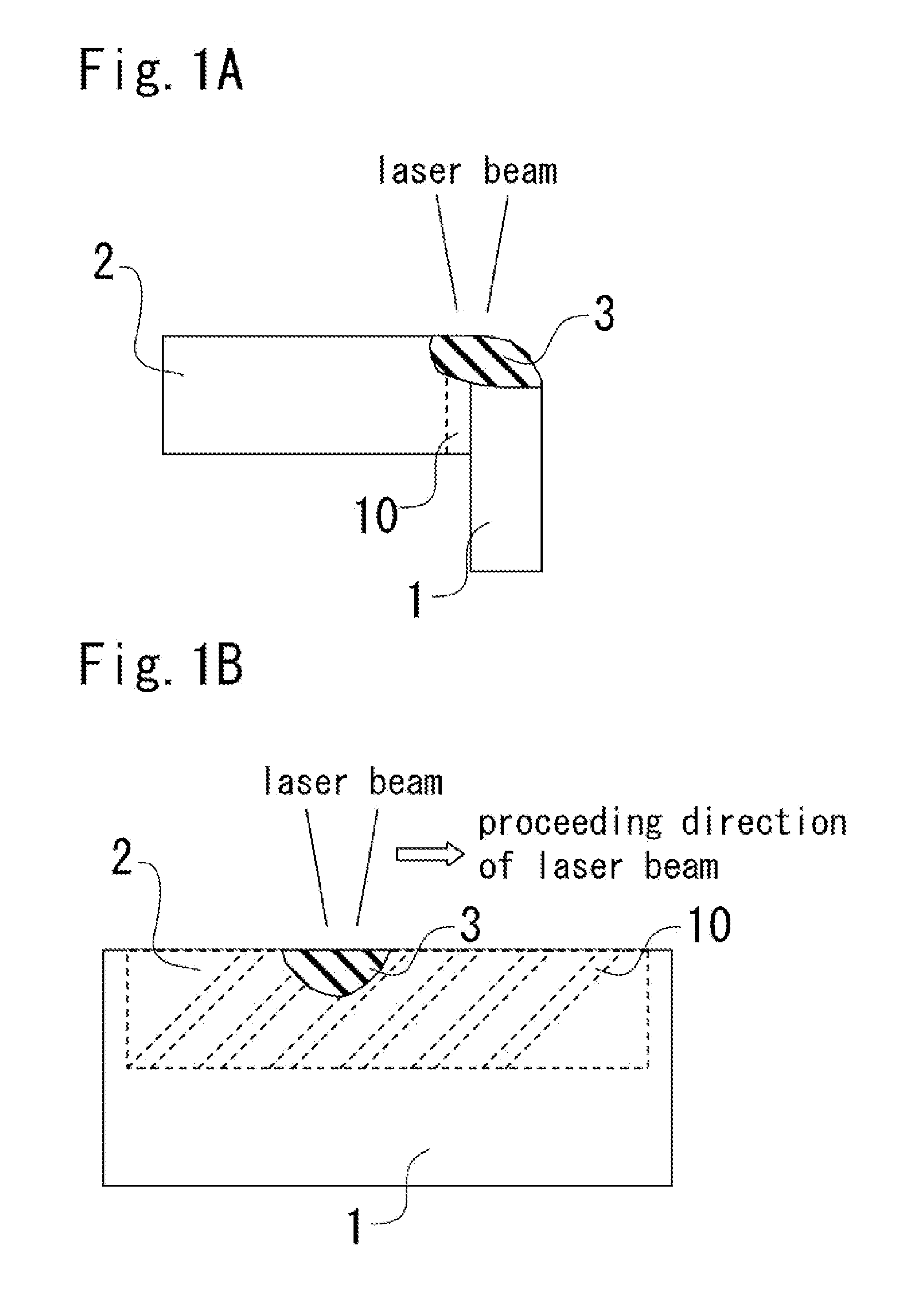
[0046]An embodiment of the present invention will be described in detail with reference to drawings as follows. FIGS. 1A and 1B show a method of the present invention for weld-sealing a cell; FIG. 1A is a longitudinal sectional view of the joint, and FIG. 1B shows the joint seen through from the front surface of the outer can 1.

[0047]According to the method of the present invention, a cell is manufactured by joining a sealing body 2 to the opening of an outer can 1, and welding the joint using a laser beam as shown in FIGS. 1A and 1B. The sealing body 2 has a plurality of grooves 10 on its outer peripheral surface. The grooves 10 are communicated with the upper and lower ends of the sealing body 2. As a result, the deepest part of a melting section 3, which is formed when the materials of the outer can 1 and of the sealing body 2 are melted by the laser beam, is located below the upper ends of the grooves 10.

[0048]This allows the gas 4 generated by the heat of the laser beam to smoo...


PUM

PropertyMeasurementUnit
widthsaaaaaaaaaa
distanceaaaaaaaaaa
widthaaaaaaaaaa

Abstract

A method for manufacturing a sealed cell includes the step of welding the joint between an outer can and a sealing body by applying high-energy radiation. Grooves are formed on the outer peripheral surface of the sealing body and/or a portion of the inner peripheral surface of the outer can, the portion facing the outer peripheral surface of the sealing body, the grooves being communicated with at least one of inside and outside the cell. A groove-forming region is formed of a plurality of the grooves having widths of 70 to 600 μm and spacings of 70 to 600 μm therebetween. The welding step applies the beam so that the deepest part of a melting section formed when the materials of the outer can and of the sealing body are melted by the beam can be located below the upper ends of the grooves forming the groove-forming region.

Description

BACKGROUND OF THE INVENTION[0001]1. Field of the Invention[0002]The present invention relates to a method for manufacturing a sealed cell, and more particularly, to a method for weld-sealing the outer can with a sealing body.[0003]2. Background Art[0004]Prismatic sealed cells have been used as power sources for driving various electronic devices because they can be easily installed therein.[0005]Such a sealed cell is manufactured by joining a sealing body to the opening of the outer can, and welding the joint using high-energy radiation such as laser beam. In this method, insufficient weld strength may cause cracks in the welded spot when the cell is dropped or subjected to other impact. The cracks may cause leakage of the electrolytic solution, and entry of oxygen or moisture into the cell, thereby reducing cell performance.[0006]One approach to solving these problems is to improve the weld strength by increasing laser beam intensity, and hence, increasing the penetration depth of ...

Claims


Application Information

Patent Timeline
Patent Type & Authority Applications(United States)
IPC IPC(8): H01M2/02H01M50/103
CPCY10T29/4911H01M2/02B23K26/206B23K26/26B23K26/32B23K33/004B23K2101/12B23K2101/38B23K2103/10Y02E60/10H01M50/169H01M50/15H01M50/103
Inventor HOSOKAWA, HIROSHIYAMAMOTO, HARUHIKO
Owner SANYO ELECTRIC CO LTD
Why Eureka
Try Eureka