Engine cooling system control

a technology for cooling systems and engines, applied in the direction of machines/engines, mechanical equipment, instruments, etc., can solve the problem of not being clear whether the temperature of coolant is increasing or decreasing, and achieve the effect of reducing the likelihood of false indication of degradation and enabling the accuracy and reliability of diagnostic routines

Inactive Publication Date: 2013-10-03
FORD GLOBAL TECH LLC
View PDF9 Cites 30 Cited by
  • Summary
  • Abstract
  • Description
  • Claims
  • Application Information

AI Technical Summary

Benefits of technology

[0006]In this way, by evaluating the functionality of the valve only during conditions when the tested function is likely to provide reliable results (that is, a reliable and accurately measurable temperature difference...

Problems solved by technology

For example, if even one of the cooling system valves is degraded, it may not be clear whether an increase in coo...

Method used


Image

  • Engine cooling system control
  • Engine cooling system control
  • Engine cooling system control

Examples


Embodiment Construction

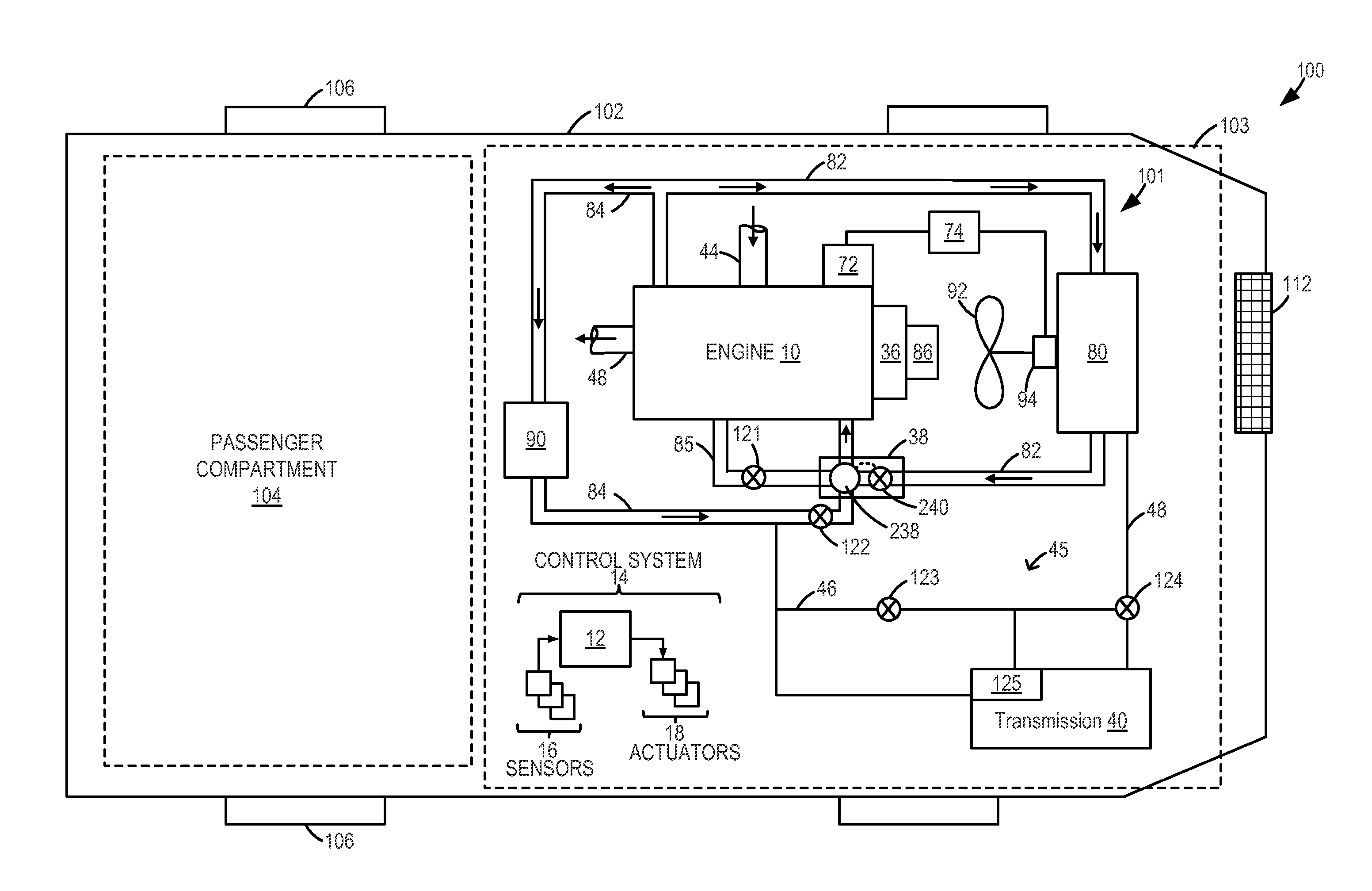
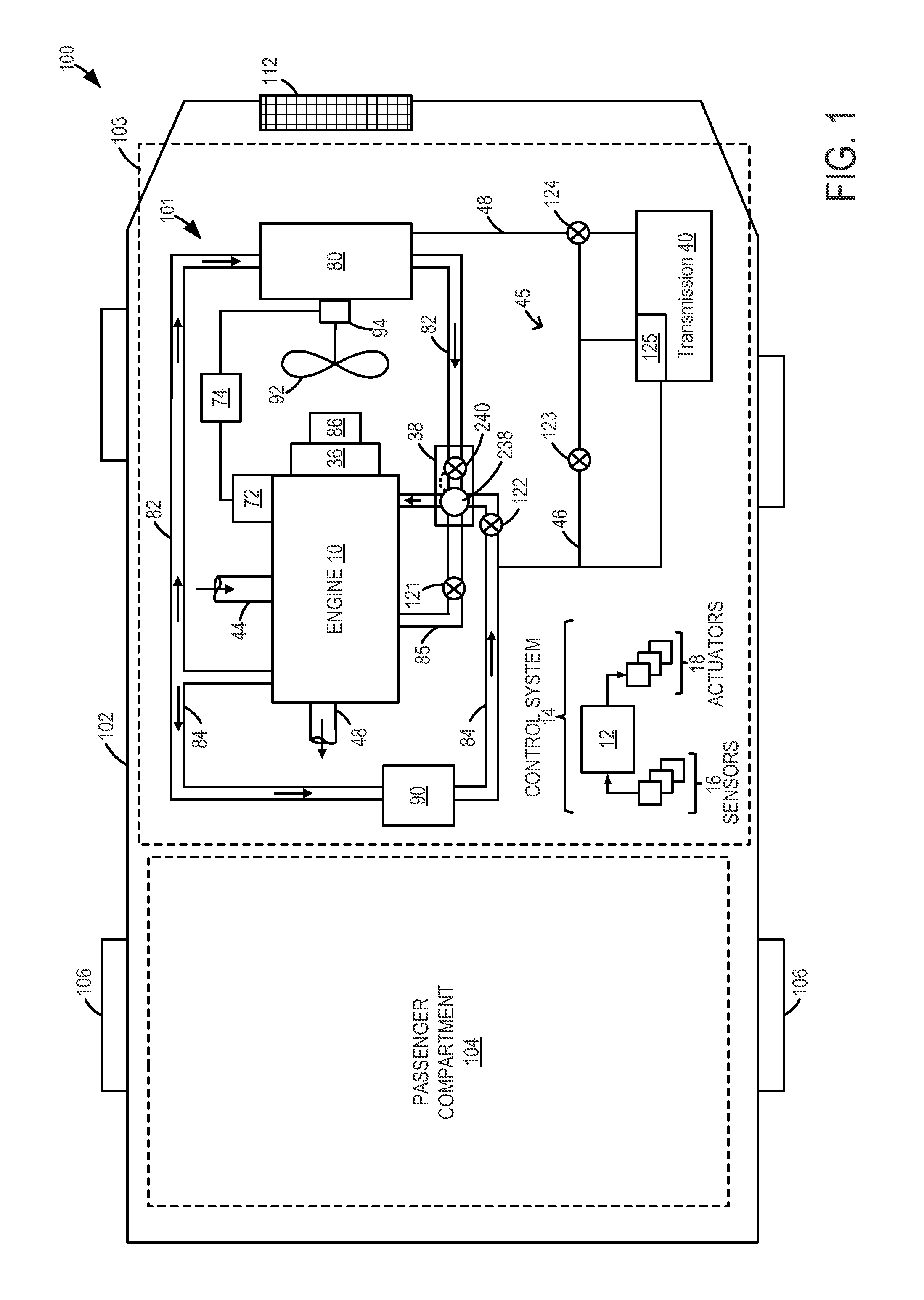
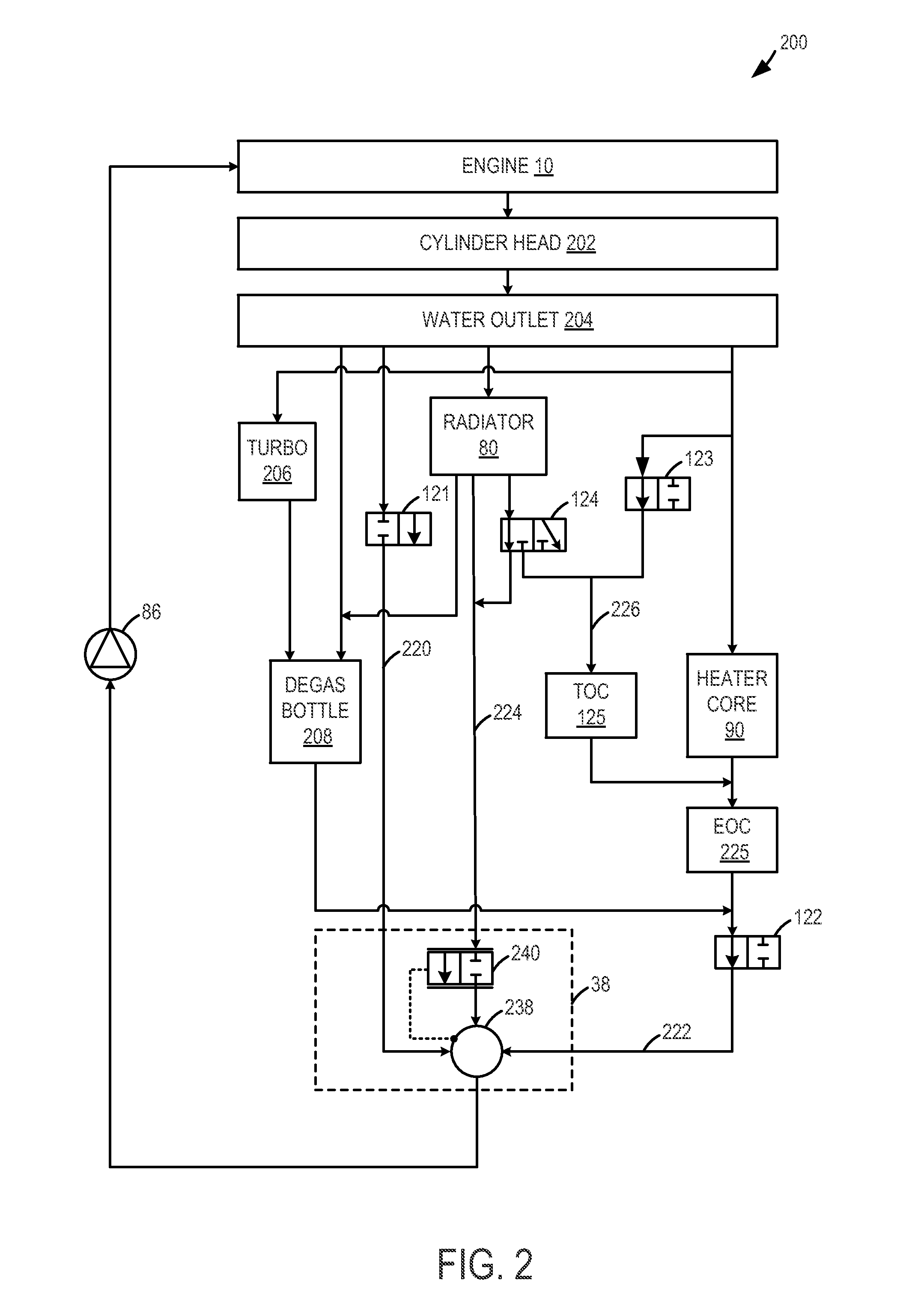
[0020]Methods and systems are provided for operating a cooling system (such as the cooling system of FIG. 1) coupled to an engine, transmission and passenger compartment of a vehicle system (such as the vehicle system of FIG. 1). Based on engine operating conditions, the position of one or more valves of the cooling system may be adjusted to thereby stagnate an amount of coolant in one region of the cooling system while circulating a remaining amount of coolant through a thermostat of the cooling system. By doing so, temperature differentials may be created at different regions of the cooling system to provide engine operating benefits. In addition, the same differentials may be used to diagnose various cooling system components. An engine controller may be configured to perform control routines, such as the routine of FIG. 3, to adjust the position of the various valves during an engine cold start to stagnate coolant at the engine, thereby expediting warm-up of the coolant in close...


PUM


Abstract

Methods and systems are provided for expediting engine system heating by stagnating coolant in one of a plurality of loops in an engine cooling system. Degradation of the various valves and thermostats of the cooling system can be diagnosed by adjusting the valve and monitoring changes in one or more of coolant temperature, transmission temperature and cabin temperature. Based on engine operating conditions, the various valves may be adjusted to vary coolant temperature in different regions of the cooling system, thereby providing fuel economy benefits.

Description

TECHNICAL FIELD[0001]The present application relates to methods and systems for diagnosing an engine cooling system.BACKGROUND AND SUMMARY[0002]Vehicles may include cooling systems configured to reduce overheating of an engine by transferring the heat to ambient air. Therein, coolant is circulated through the engine block to remove heat from the hot engine, and the heated coolant is then circulated through a radiator near the front of the vehicle. Heated coolant may also be circulated through a heat exchanger to heat a passenger compartment. The cooling system may include various components such as various valves and thermostats.[0003]The various cooling system components may need to periodically diagnosed. For example, if even one of the cooling system valves is degraded, it may not be clear whether an increase in coolant temperature is due to a change in valve position or due to an unexpected overheating of an engine system component. As such, various diagnostic routines may be us...

Claims


Application Information

Patent Timeline
IPC IPC(8): F01P5/14
CPCF01P11/16F01P3/20G07C5/0808F01P2060/04F01P2060/18F01P2037/02
Inventor PURSIFULL, ROSS DYKSTRAJENTZ, ROBERT ROY
Owner FORD GLOBAL TECH LLC
Why Eureka
Try Eureka