
Reflow oven and methods of treating surfaces of the relfow oven

a soldering oven and surface treatment technology, applied in the direction of machines/engines, non-electric welding apparatus, packaging, etc., can solve the problems of contaminating or otherwise compromising the attachment of components to printed circuit boards, both flux removal systems suffer from well-known shortcomings, and the removal of flux on the chamber walls is generally not addressed

Active Publication Date: 2013-10-03
ILLINOIS TOOL WORKS INC
View PDF2 Cites 17 Cited by
  • Summary
  • Abstract
  • Description
  • Claims
  • Application Information

AI Technical Summary

Benefits of technology

This patent is about a reflow oven used for joining electronic components to a substrate. It describes a method for treating the surfaces of the oven that are exposed to contaminants, including flux. The method includes applying an intermediate layer on the surfaces of the reflow oven, which helps remove the contaminants. The intermediate layer can be sprayed or applied with adhesive, and can be peeled off or removed with a chemical. After removing the intermediate layer, a new intermediate layer can be applied to the surfaces to further remove any remaining contaminants. The technical effects of this patent include improving the cleanliness and efficiency of the reflow oven process.

Problems solved by technology

Both flux removal systems suffer from well-known shortcomings.
Over time, the flux collected on the chamber walls create problems during production as excess flux may drip back onto actual production printed circuit boards, thereby potentially contaminating or otherwise compromising the attachment of components onto the printed circuit boards.
During such scheduled maintenance, the removal of flux on chamber walls is generally not addressed.
Thus, ongoing flux contamination exposed to the printed circuit boards being produced would remain.
Over time, excess flux may also cause premature failures of components of the reflow oven, including blowers designed to facilitate air circulation within the reflow oven chamber.

Method used

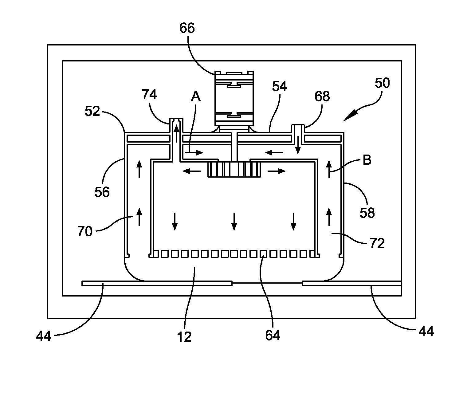
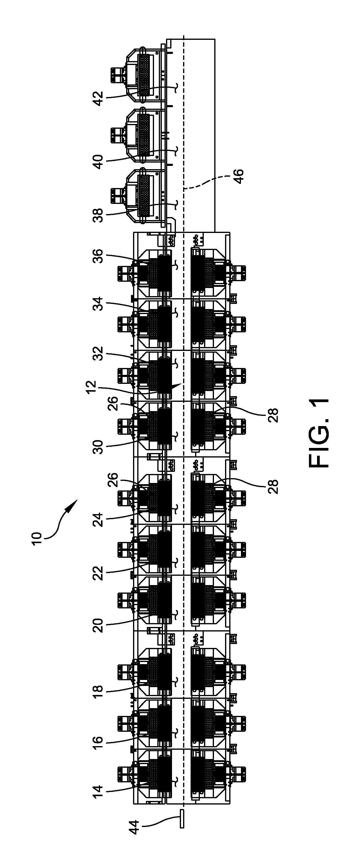
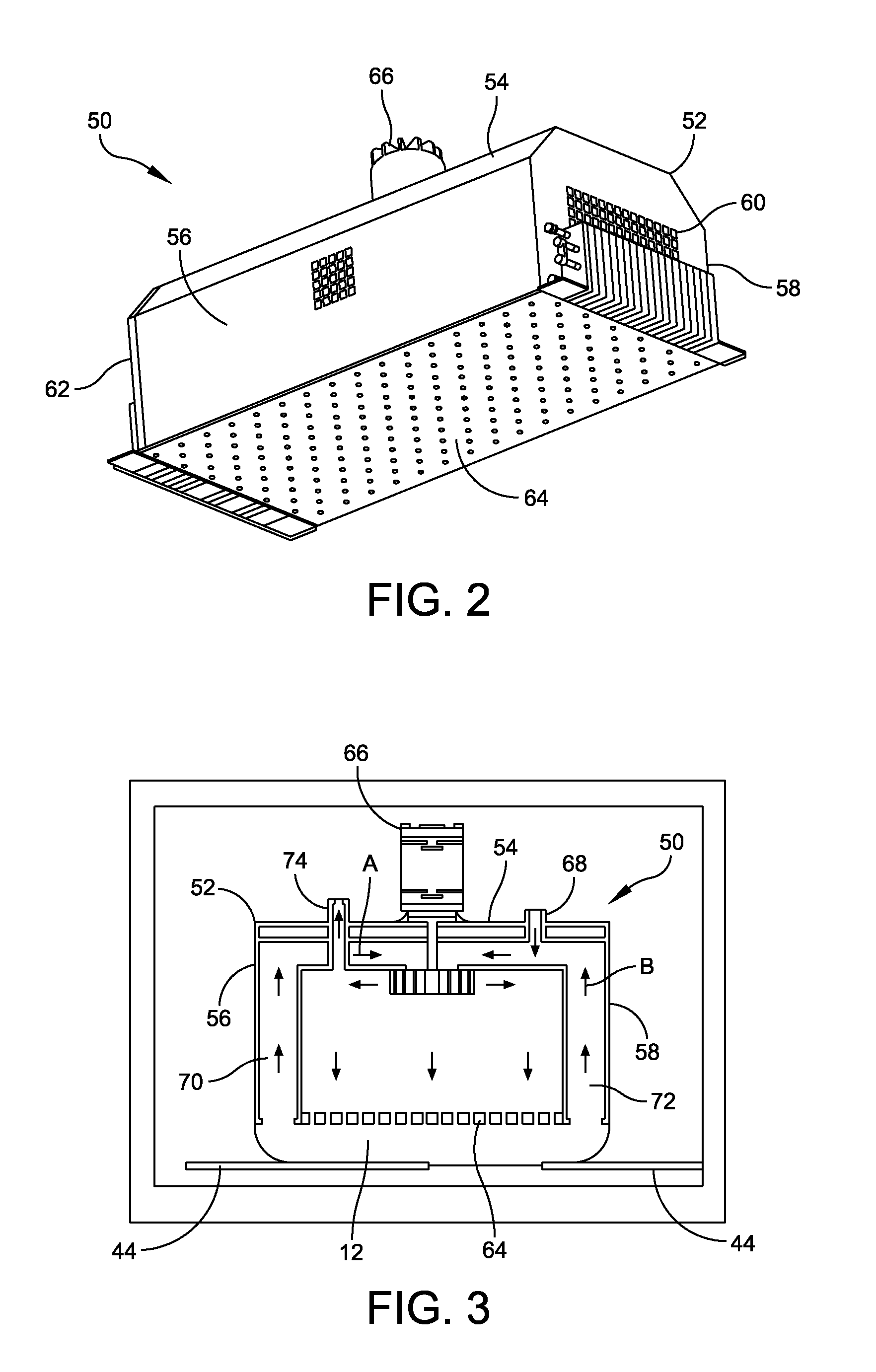

Image

  • Reflow oven and methods of treating surfaces of the relfow oven
  • Reflow oven and methods of treating surfaces of the relfow oven
  • Reflow oven and methods of treating surfaces of the relfow oven

Examples


Embodiment Construction

[0016]For the purposes of illustration only, and not to limit the generality, the present disclosure will now be described in detail with reference to the accompanying figures. This disclosure is not limited in its application to the details of construction and the arrangement of components set forth in the following description or illustrated in the drawings. The principles set forth in this disclosure are capable of other embodiments and of being practiced or carried out in various ways. Also the phraseology and terminology used herein is for the purpose of description and should not be regarded as limiting. The use of “including,”“comprising,”“having,”“containing,”“involving,” and variations thereof herein, is meant to encompass the items listed thereafter and equivalents thereof as well as additional items.

[0017]Solder paste is routinely used in the assembly of printed circuit boards, where the solder paste is used to join electronic components to the circuit board. Solder paste...


PUM

PropertyMeasurementUnit
temperatureaaaaaaaaaa

Abstract

A reflow oven used to join electronic components to a substrate includes a chamber housing having surfaces that are in contact with heated air mixed with contaminants, including flux, and an intermediate layer selectively applied to the surfaces of the chamber housing. The reflow oven may include fabricating the intermediate layer with a foam material, including foaming polymers, e.g., epoxy, polyurethane, polyester, and silicone, or a non-foam material, including non-foaming polymers, e.g., polytetrafluoroethylene and polyimide. A method of treating surfaces of a reflow oven exposed to contaminants, including flux, is further disclosed.

Description

BACKGROUND OF THE DISCLOSURE[0001]1. Field of the Disclosure[0002]This application relates generally to the surface mount of electronic components onto a printed circuit board by employing a reflow process, and more particularly to a reflow soldering oven that is designed to heat the printed circuit board during the reflow process.[0003]2. Discussion of Related Art[0004]In the fabrication of printed circuit boards, electronic components are often surface mounted to a bare board by a process known as “reflow soldering.” In a typical reflow soldering process, a pattern of solder paste is deposited onto the circuit board, and the leads of one or more electronic component are inserted into the deposited solder paste. The circuit board is then passed through an oven where the solder paste is reflowed (i.e., heated to a melt or reflow temperature) in the heated zones and then cooled in a cooling zone to electrically and mechanically connect the leads of the electronic component to the cir...

Claims


Application Information

Patent Timeline
Patent Type & Authority Applications(United States)
IPC IPC(8): B23K31/02B32B37/00B05D7/22B23K3/04
CPCB23K1/008F27B9/3077F27B9/32F27B9/34F27D1/1678Y10T156/10H05K3/3494B23K1/0016B23K1/012B23K1/203B23K2201/42F27D17/008B23K2101/42
Inventor NGAI, DOUGLASTAY, JOO YONGLIU, WEN-FENGLOERA, ROBERTO P.COOK, STEVEN DWADE
Owner ILLINOIS TOOL WORKS INC
Learn More