Tubular linear motor

a linear motor and tube technology, applied in the direction of dynamo-electric machines, electrical apparatus, windings, etc., can solve the problems of increasing the thrust force, limiting the expansion of the thrust force, and reducing the effect of the magnetic attractive force caused by the deviation of the core, so as to increase the winding number of the coil and the thrust force, the effect of reducing the influence of the core deviation on the magnetic attractive for

Inactive Publication Date: 2013-10-03
SANYO DENKI CO LTD
View PDF19 Cites 2 Cited by
  • Summary
  • Abstract
  • Description
  • Claims
  • Application Information

AI Technical Summary

Benefits of technology

[0016]In the tubular linear motor according to the present invention, the coil extends over the teeth from the inner side of the slot toward the magnetic exciter, so that the coil is arranged in both the inner and outer sides of the slot. Therefore, it is possible to increase the winding number of the coil and the thrust force of the rectilinear motion.
[0017]Since the coil extends over the teeth from the inner side of the slot toward the magnetic exciter while a mechanical gap is reserved, the diametrical length of the tooth is smaller than the di

Problems solved by technology

Therefore, if a core deviation (eccentric core) is generated in the center shaft, a thrust force ripple and a cogging force unfortunately increase due to influence of the magnetic attractive force.
Therefore, the magnetic flux can reach farther, whereas an average magnetic flux is low, and there is a limitation to increase th

Method used


Image

  • Tubular linear motor
  • Tubular linear motor
  • Tubular linear motor

Examples


embodiment 1

[Configuration of Tubular Linear Motor]

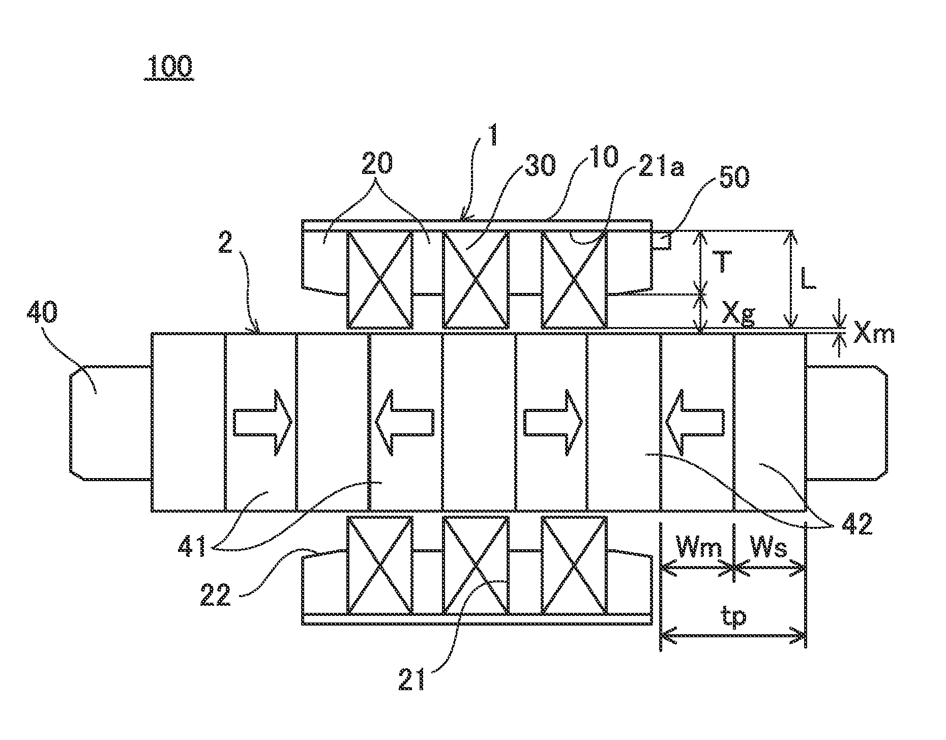
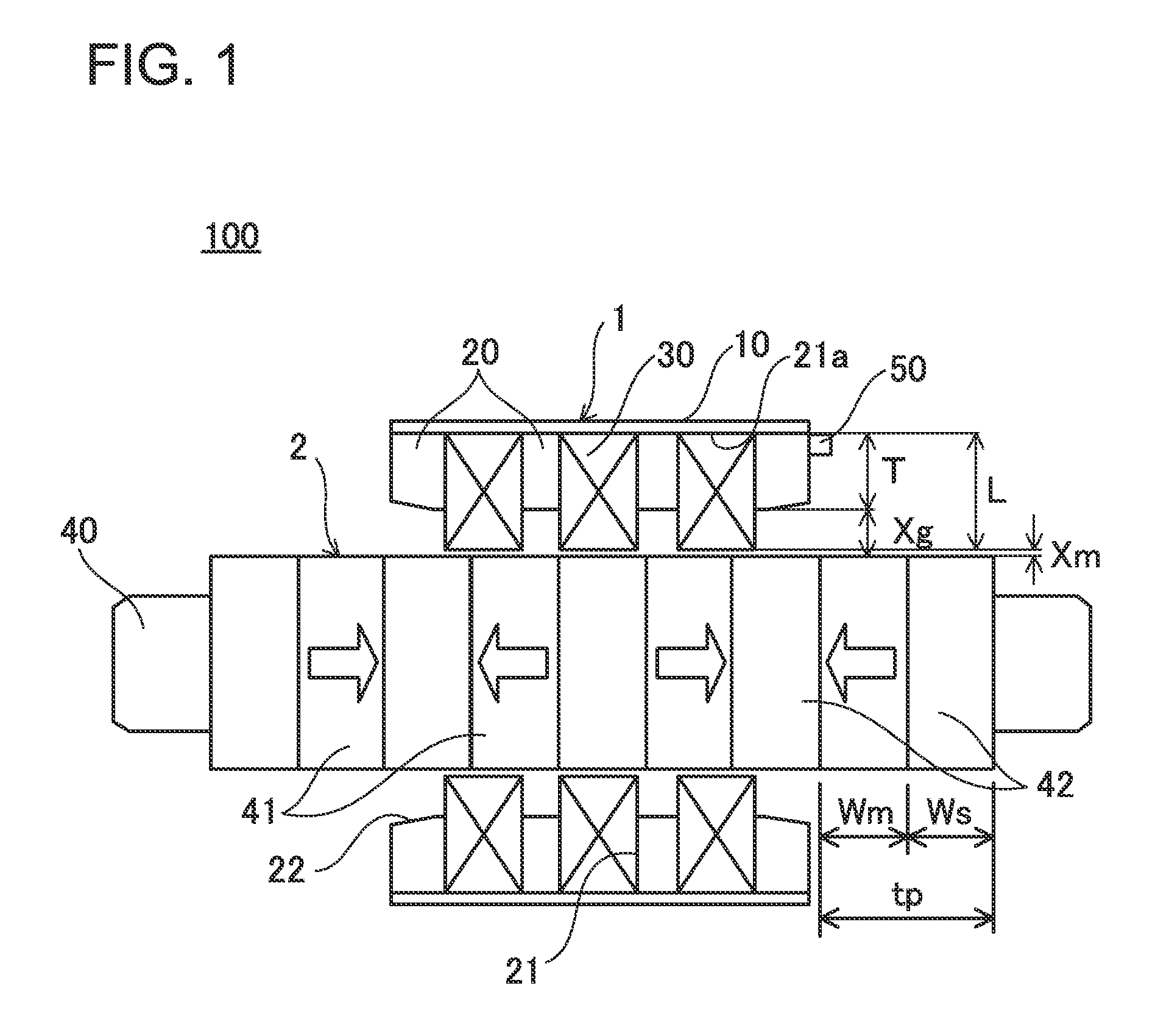
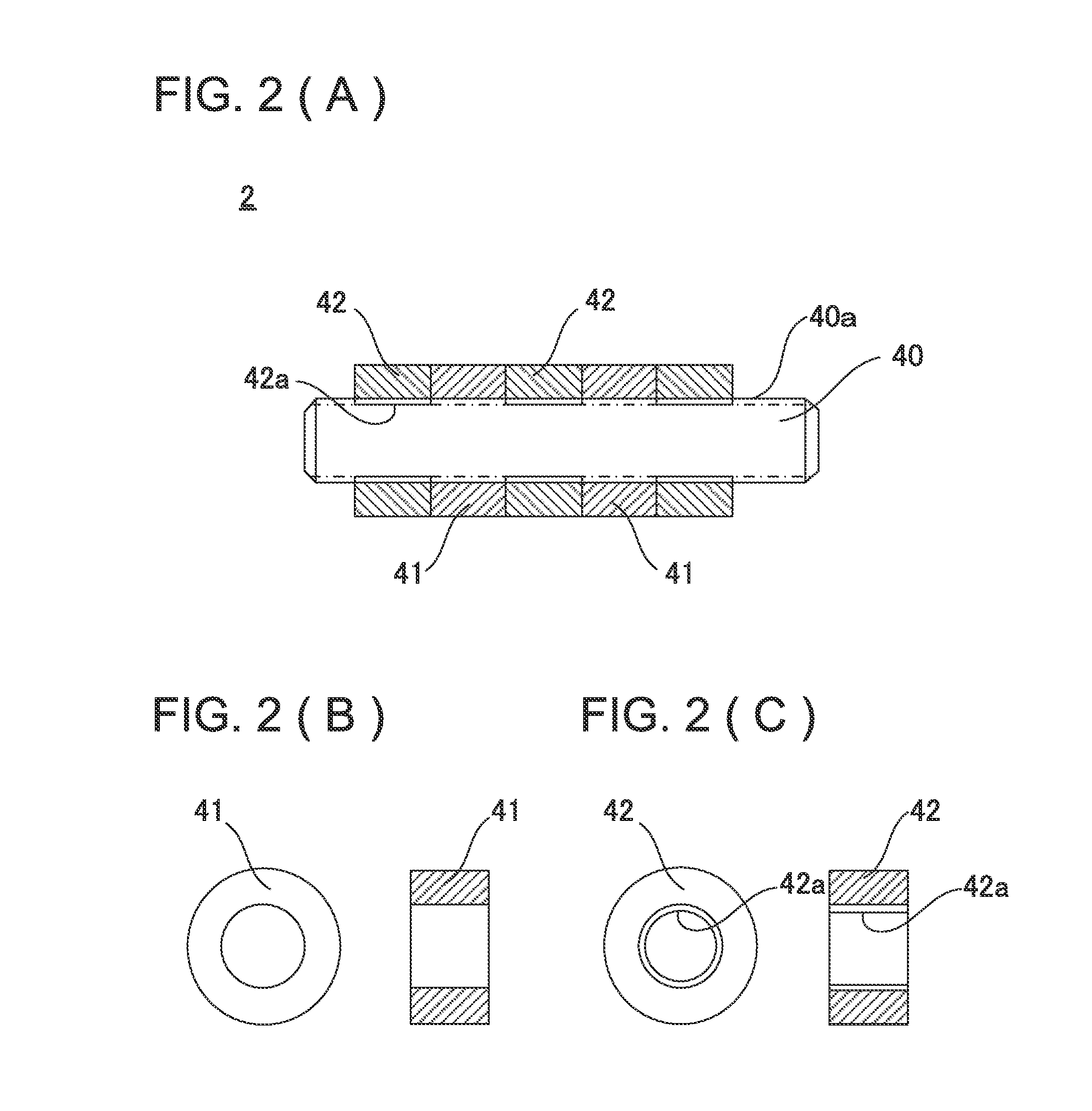
[0032]First, a configuration of a tubular linear motor according to Embodiment 1 will be described with reference to FIGS. 1 and 2A to 2C. FIG. 1 is a schematic cross-sectional view illustrating a tubular linear motor according to Embodiment 1.

[0033]As illustrated in FIG. 1, the tubular linear motor 100 according to Embodiment 1 includes an armature 1 and a magnetic exciter 2.

[0034]The armature 1 has a yoke 10, teeth 20, and a coil 30. According to Embodiment 1, the armature 1 serves as a mover.

[0035]The yoke 10 is a tubular magnetic metal member having a cylindrical shape and the like. The yoke 10 blocks the magnetic flux from the magnetic exciter 2 to maximize an electromagnetic induction effect of the permanent magnet 41 described below. The yoke 10 also prevents peripherals of the tubular linear motor 100 from being affected by the magnetic field caused by the electromagnetic induction.

[0036]The yoke 10 may be made of, for example, but not ...

embodiment 2

[0068]Next, a tubular linear motor 200 according to Embodiment 2 will be described with reference to FIG. 4. FIG. 4 is a schematic cross-sectional view illustrating the tubular linear motor according to Embodiment 2. In the following description, like reference numerals denote like elements as in the tubular linear motor 100 according to Embodiment 1, and description thereof will not be repeated.

[0069]As illustrated in FIG. 4, the tubular linear motor 200 according to Embodiment 2 has a similar configuration to that of Embodiment 1 except for shapes of the coil 230 and the teeth 220 of the armature 1.

[0070]In the coil 230 according to Embodiment 2, a width dl of a portion of the coil extending over the tooth 220 from the opening end of the tooth 220 toward the magnetic exciter 2 is smaller than a width D of a portion of the coil stored in the slot 21. That is, the cross section of the coil 230 is stepped with a step portion 231.

[0071]The leading edge of the tooth 220 is provided wit...

embodiment 3

[0073]Next, a tubular linear motor 300 according to Embodiment 3 will be described with reference to FIGS. 5 and 6. FIG. 5 is a schematic cross-sectional view illustrating the tubular linear motor according to Embodiment 3. In the following description, like reference numerals denote like elements as in the tubular linear motor 100 according to Embodiment 1, and description thereof will not be repeated.

[0074]As illustrated in FIG. 5, the tubular linear motor 300 according to Embodiment 3 has a similar configuration to that of Embodiment 1 except for the shape of the coil 330 of the armature 1.

[0075]In the coil 330 according to Embodiment 3, a width d2 of a portion of the coil extending from the opening end of the tooth 20 toward the magnetic exciter 2 is larger than a width D of a portion of the coil stored in the slot 21. That is, the coil 330 is formed to extend from the opening end of the tooth 20 toward the magnetic exciter 2 and be widened to the magnetic gap (teeth gap) Xg sid...


PUM


Abstract

The tubular linear motor includes an armature having a coil and a magnetic exciter having a permanent magnet provided to face the coil. The armature has a yoke that blocks a magnetic flux, teeth that partition a slot for storing the coil, and the coil that is arranged to extend over the teeth from an inner side of the slot toward the magnetic exciter while a mechanical gap is reserved between the magnetic exciter and the coil. The magnetic exciter has a plurality of permanent magnets by interposing a soft magnetic body.

Description

BACKGROUND[0001]1. Technical Field[0002]The present invention relates to a tubular linear motor that exerts a rectilinear motion to a driving target based on an electromagnetic force.[0003]2. Description of Related Arts[0004]In general, a tubular linear motor includes a magnetic exciter in which a plurality of permanent magnets is arranged in series such that different magnetic poles face each other, and an armature having a coil, arranged to surround the magnetic exciter and slidable along an axial direction of the magnetic exciter.[0005]In the tubular linear motor, an electric current flows through the coil of the armature to intersect a magnetic flux generated by the permanent magnet of the magnetic exciter, so that a driving force in an axial direction is generated in the coil based on the electromagnetic induction effect to move the armature.[0006]As a technique relating to the armature of the linear motor, there are disclosed a linear synchronous motor and a linear actuator, i...

Claims


Application Information

Patent Timeline
IPC IPC(8): H02K41/03
CPCH02K41/031H02K3/48H02K41/02H02K1/2713H02K21/24
Inventor TANG, YUQIMISAWA, YASUSHI
Owner SANYO DENKI CO LTD
Why Eureka
Try Eureka