
Capacitive Supply Level Sensing Circuit and Method

a sensing circuit and capacitive supply technology, applied in the field of capacitive supply level sensing circuit and method, circuit and method for measuring toner or ink level, can solve the problems of leakage of ports, breakage of other components located inside and outside the imaging unit, and impair the future performance of the imaging unit, so as to achieve robust and cost-effective connection

Active Publication Date: 2013-10-03
LEXMARK INT INC
View PDF1 Cites 19 Cited by
  • Summary
  • Abstract
  • Description
  • Claims
  • Application Information

AI Technical Summary

Benefits of technology

Example embodiments provide a robust and capacitance-based toner level sensing system for sensing toner in a replaceable unit for an electrophotographic imaging apparatus. The system measures toner levels in a developer unit of the apparatus using a capacitor that serves both as a sensor and a doctor blade for the unit. The system includes an AC signal generator, conversion circuitry, and a sample and hold circuitry. The AC signal generator is coupled between the system ground and a local ground to provide a more robust connection for the capacitor. The conversion circuitry converts the alternating current of the first signal to a substantially DC voltage value that is based upon the capacitance of the capacitor under test and the reference capacitor. The toner level sensing circuitry also includes circuitry for reducing offset voltages and generating an offset voltage for canceling corresponding offset voltage in the circuitry. The technical effects of this patent include providing a reliable and accurate method for measuring toner levels in the developer unit, and improving the overall performance and reliability of the toner level sensing system.

Problems solved by technology

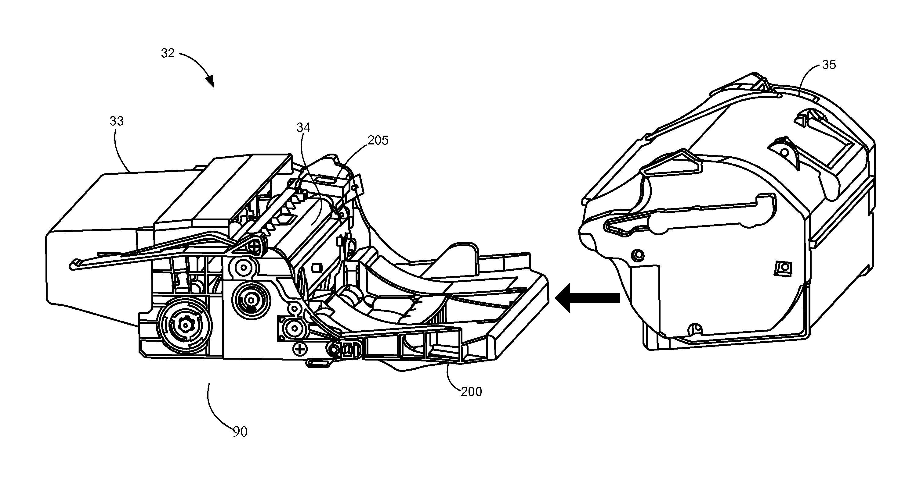
For example, if the imaging unit sump holds too much toner, toner may pack in the imaging unit sump, leak out of the ports and eventually break other components located inside and outside the imaging unit.
If the toner level in the imaging unit sump gets too low, the toner adder roll may starve, causing a doctor blade of the imaging unit to film and damage the developer roll which may eventually impair the future performance of the imaging unit.
However, these methods may not be accurate due to variability in factors such as the environment, developer roll age, toner patch sensing cycles, and toner transfer parameters.
Unfortunately, the addition of moving hardware increases component complexity and opportunities for errors.
For instance, toner agitation may create unwanted toner dust in addition to the added complication of moving hardware.
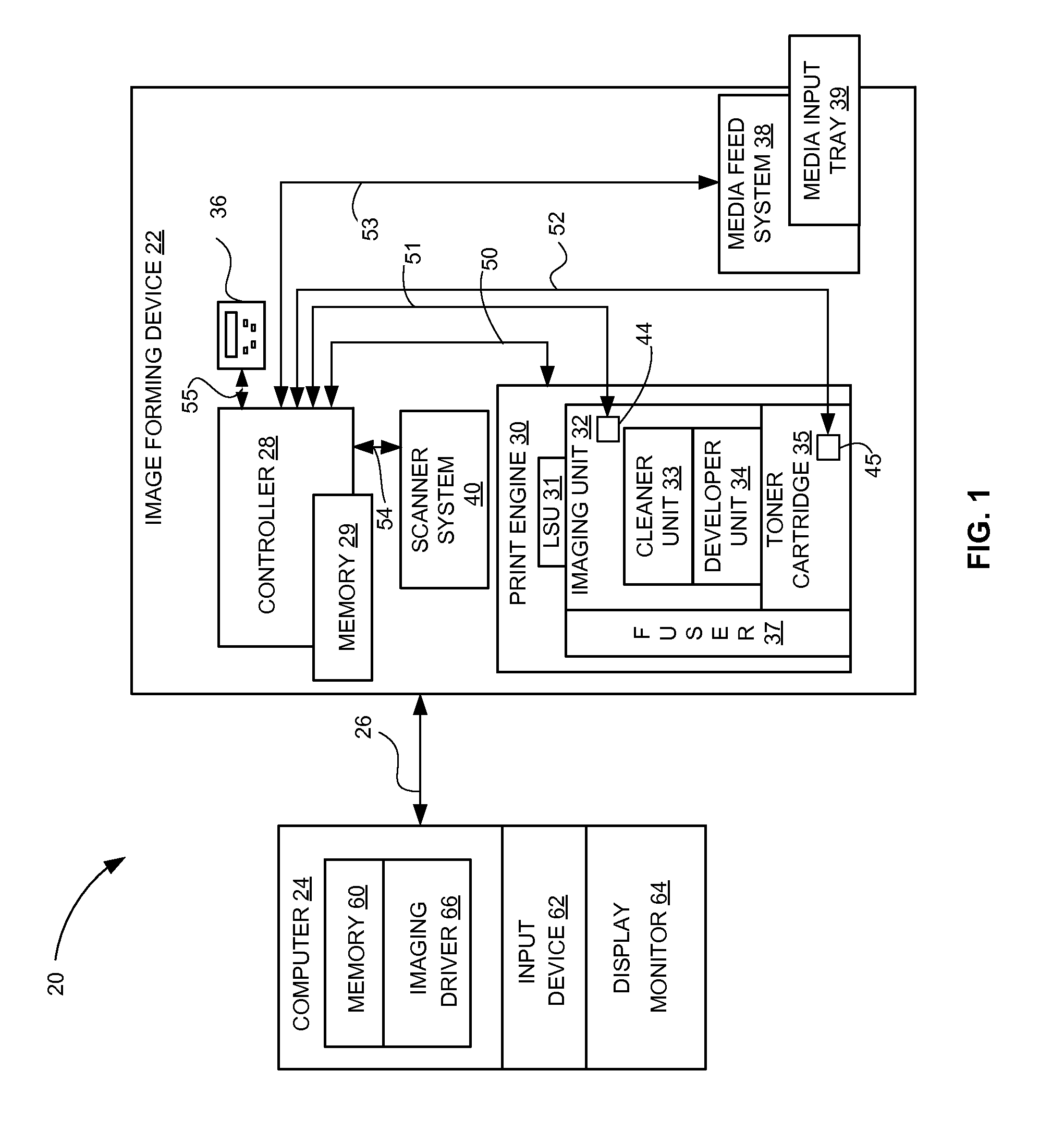
Though the circuit of FIG. 1 has been used to effectively sense toner levels in a waste toner container by solving for capacitor Cx in the above equation, the circuit is not as robust or cost effective when used in some capacitive toner level sensing applications by, for example, requiring use of flexible circuits or the like to form the plates of capacitor Cx.

Method used


Image

  • Capacitive Supply Level Sensing Circuit and Method
  • Capacitive Supply Level Sensing Circuit and Method
  • Capacitive Supply Level Sensing Circuit and Method

Examples


Embodiment Construction

[0028]It is to be understood that the invention is not limited in its application to the details of construction and the arrangement of components set forth in the following description or illustrated in the drawings. The invention is capable of other embodiments and of being practiced or of being carried out in various ways. Also, it is to be understood that the phraseology and terminology used herein is for the purpose of description and should not be regarded as limiting. The use herein of “including,”“comprising,” or “having” and variations thereof is meant to encompass the items listed thereafter and equivalents thereof as well as additional items. Unless limited otherwise, the terms “connected,”“coupled,” and “mounted,” and variations thereof herein are used broadly and encompass direct and indirect connections, couplings, and mountings. In addition, the terms “connected” and “coupled” and variations thereof are not restricted to physical or mechanical connections or couplings...


PUM


Abstract

A circuit and system for sensing a capacitance of a capacitive sensor disposed in a toner container of an electrophotographic imaging apparatus. The circuit and system may include an AC signal generator and conversion circuitry, coupled to the capacitive sensor, for detecting an AC current appearing on the capacitive sensor and converting the detected AC current to a substantially DC voltage, relative to a local ground, the local ground serving as a ground reference for the conversion circuitry. The AC signal generator is coupled between the local ground and a system ground. Physically separating the AC signal generator from the capacitive sensor allows for parts of the capacitive sensor to be used to perform other functions in the toner container.

Description

CROSS REFERENCES TO RELATED APPLICATIONS[0001]This application is related to U.S. patent application Ser. No. 13 / 340,789, filed Dec. 30, 2011, entitled “Capacitive Toner Level Sensor,” the content of which is hereby incorporated by reference herein in its entirety.STATEMENT REGARDING FEDERALLY SPONSORED RESEARCH OR DEVELOPMENT[0002]None.REFERENCE TO SEQUENTIAL LISTING, ETC[0003]None.BACKGROUND[0004]1. Technical Field[0005]The present disclosure relates to imaging devices. More particularly, it relates to a circuit and method for measuring toner or ink levels in the imaging unit of an imaging device.[0006]2. Description of the Related Art[0007]Image forming devices such as copiers, laser printers, facsimile machines and the like typically use one or more toner containers to hold toner supply used for image forming processes. In some image forming devices, a large toner supply is provided in a reservoir in a toner cartridge that mates with a separate imaging unit. The imaging unit may...

Claims


Application Information

Patent Timeline
Patent Type & Authority Applications(United States)
IPC IPC(8): G01R27/26
CPCG01F23/266
Inventor AHNE, ADAM JUDEBARRY, RAYMOND JAY
Owner LEXMARK INT INC
Learn More