Robot system and robot

a robot and robot arm technology, applied in the direction of manipulators, coupling device connections, electrical devices, etc., can solve the problems of cable breakage and narrow operating range of the robot arm

Inactive Publication Date: 2013-10-03
SEIKO EPSON CORP
View PDF8 Cites 28 Cited by
  • Summary
  • Abstract
  • Description
  • Claims
  • Application Information

AI Technical Summary

Benefits of technology

[0007]An advantage of some aspects of the invention is to provide a robot system and a robot that can route a flexible long object, such as a cable, connected to a connector with ease.

Problems solved by technology

However, in such a cable routing mode (a direction in which a cable is drawn), when a connector having packing is used, depending on, for example, the height of the ceiling of a room in which the robot is placed, the ceiling and the cable collide with each other (make contact with each other).
In this case, with the movement of the robot arm, the cable breaks due to the friction between the cable and the ceiling.
Moreover, when the arm rotates, since the other arm and the cable collide with each other, the operating range of the robot arm becomes narrow.

Method used


Image

  • Robot system and robot
  • Robot system and robot
  • Robot system and robot

Examples


Embodiment Construction

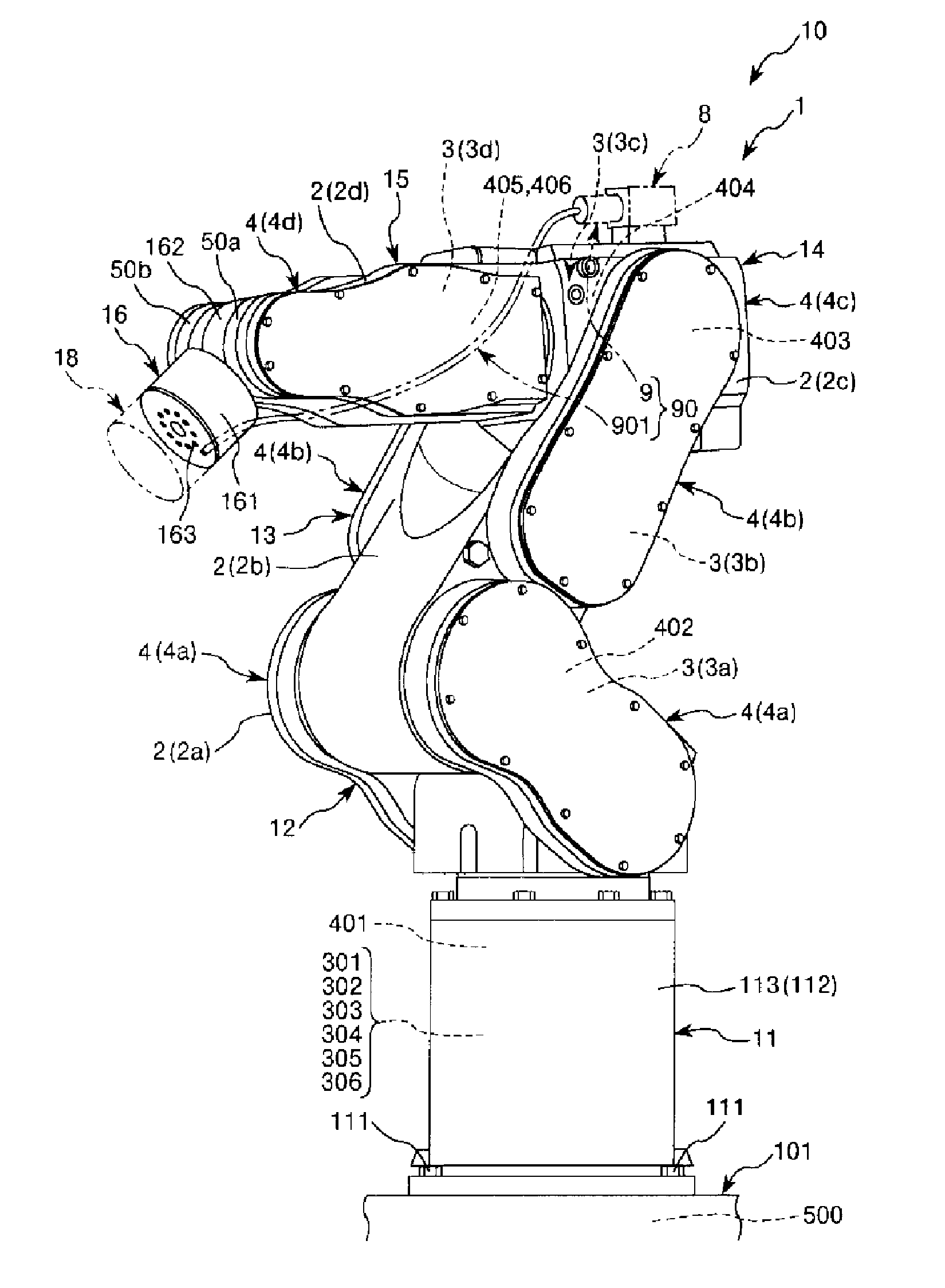
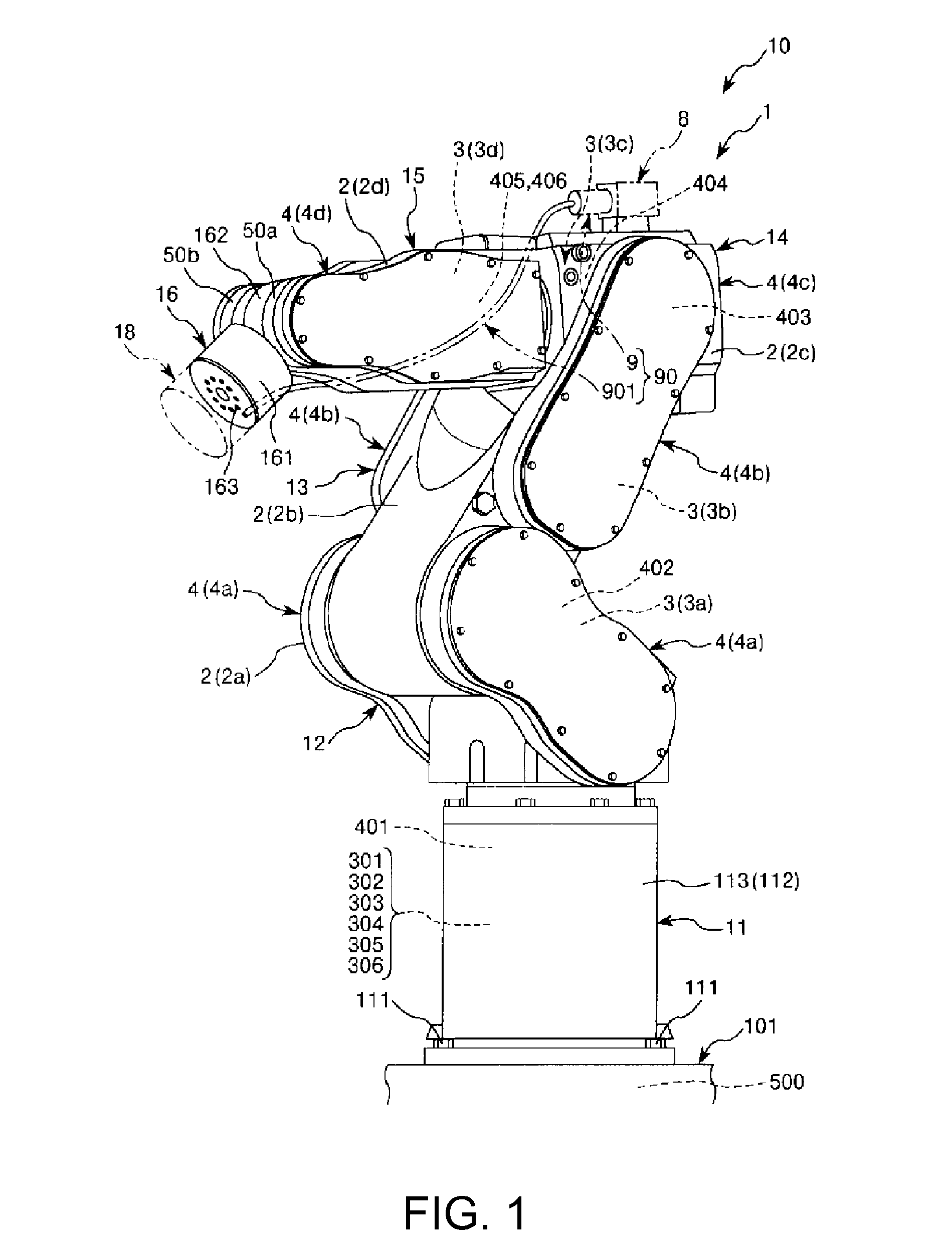
[0043]Hereinafter, based on a preferred embodiment of the invention shown in the attached drawings, a robot system and a robot of the embodiment of the invention will be described in detail.

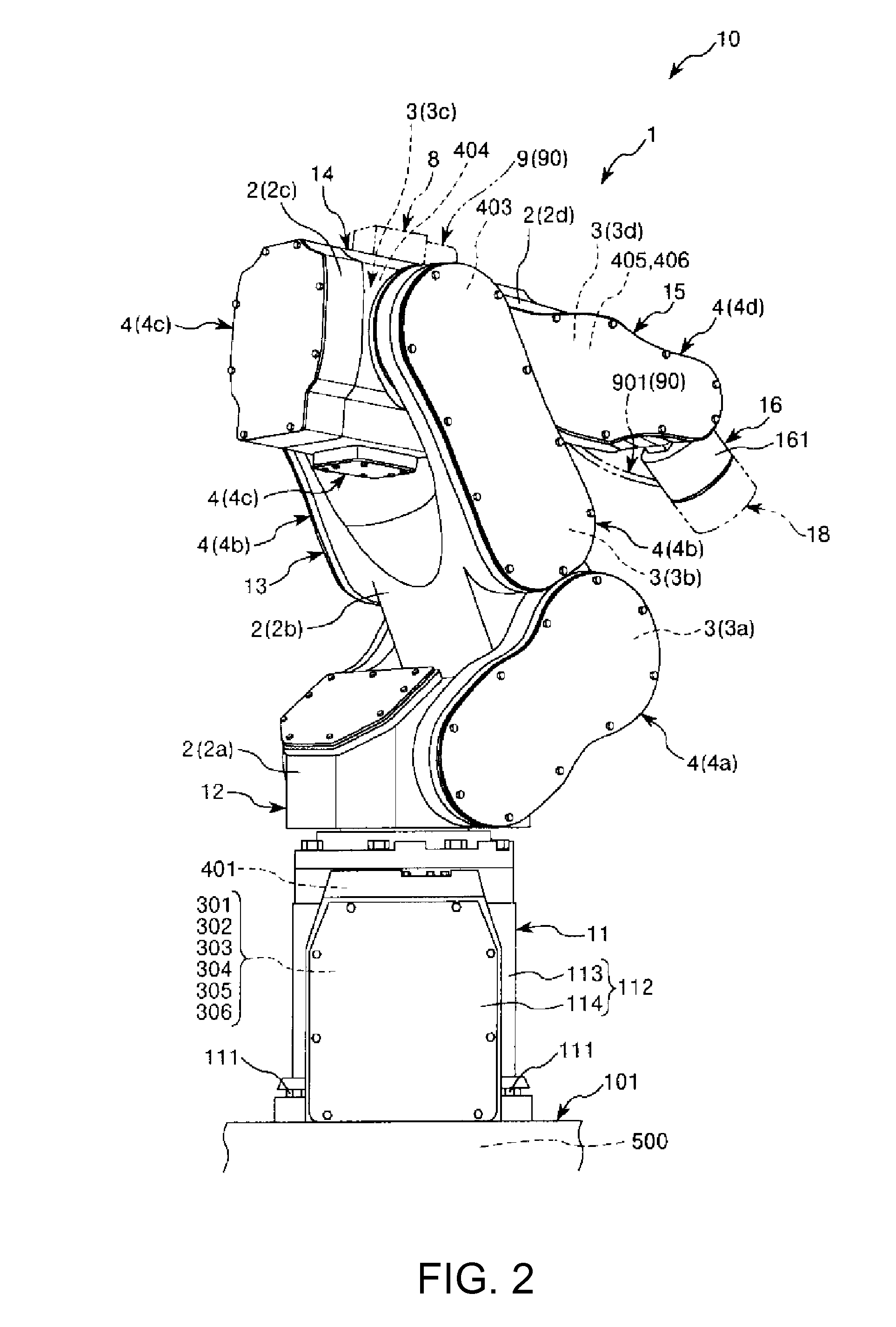
[0044]FIG. 1 is a perspective view of a robot (a robot system) of the embodiment of the invention viewed from the front, FIG. 2 is a perspective view of the robot (the robot system) of the embodiment of the invention viewed from the back, FIG. 3 is an enlarged view of an upper portion of the robot (the robot system) of the embodiment of the invention, FIG. 4 is a schematic diagram of the robot of the embodiment of the invention, FIG. 5 is a block diagram of a principal portion of the robot (the robot system) of the embodiment of the invention, FIG. 6 is a perspective view showing a usage state (a placement state) of the robot (the robot system) of the embodiment of the invention, FIG. 7 is an exploded perspective view of a typical arm of a plurality of arms of the robot of the embodiment of the i...


PUM


Abstract

A robot includes a connector receiving portion to which a connector is connected, the connector having a hollow connector housing and first packing and second packing that maintain the hermeticity of the connector housing. The robot further includes an arm and an arm that are coupled to each other. Each arm is supported in such a way as to be rotatable about a rotation axis. Moreover, the connector receiving portion is placed in the arm in such a way that a direction in which the connector connected to the connector receiving portion is drawn coincides with a direction of the rotation axis.

Description

BACKGROUND[0001]1. Technical Field[0002]The present invention relates to robot systems and robots.[0003]2. Related Art[0004]In the past, a robot that is placed in a germ-free workroom filled with corrosive sterilizing gas such as hydrogen peroxide vapor and performs various operations has been known (for example, see JP-A-2005-205576 (hereinafter Patent Document 1)). Such a robot has corrosion resistance so that the sterilizing gas does not enter the robot and corrode a motor, wiring, and the like. Moreover, as a connector connected to the robot, a large connector having a sealing member such as packing is used to prevent internal corrosion.[0005]Furthermore, in the past, a robot provided with a base and a robot arm that is supported in such a way that the robot arm can be displaced with respect to the base has been known (for example, see JP-A-2010-76056 (hereinafter Patent Document 2)). In the robot described in Patent Document 2, the robot arm is formed of six arms (a first arm, ...

Claims


Application Information

Patent Timeline
Patent Type & Authority Applications(United States)
IPC IPC(8): H01R13/60
CPCH01R13/60B25J19/0029Y10S901/15
Inventor HAHAKURA, SEIJIOWA, TAKUYA
Owner SEIKO EPSON CORP
Why Eureka
Try Eureka