

Hydraulic auto-tensioner
a technology of hydraulic auto-tensioner and belt, which is applied in the direction of belt/chain/gearing, mechanical equipment, belts, etc., can solve the problems of affecting the pushing force applied to the rod, and achieve the effects of preventing belt over-tensioning, less cost, and convenient assembly
- Summary
- Abstract
- Description
- Claims
- Application Information
AI Technical Summary
Benefits of technology
Problems solved by technology
Method used
Image

Examples
Embodiment Construction
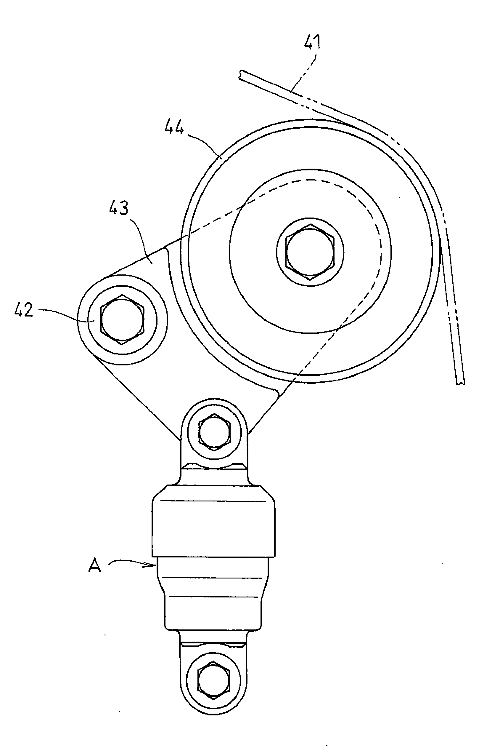
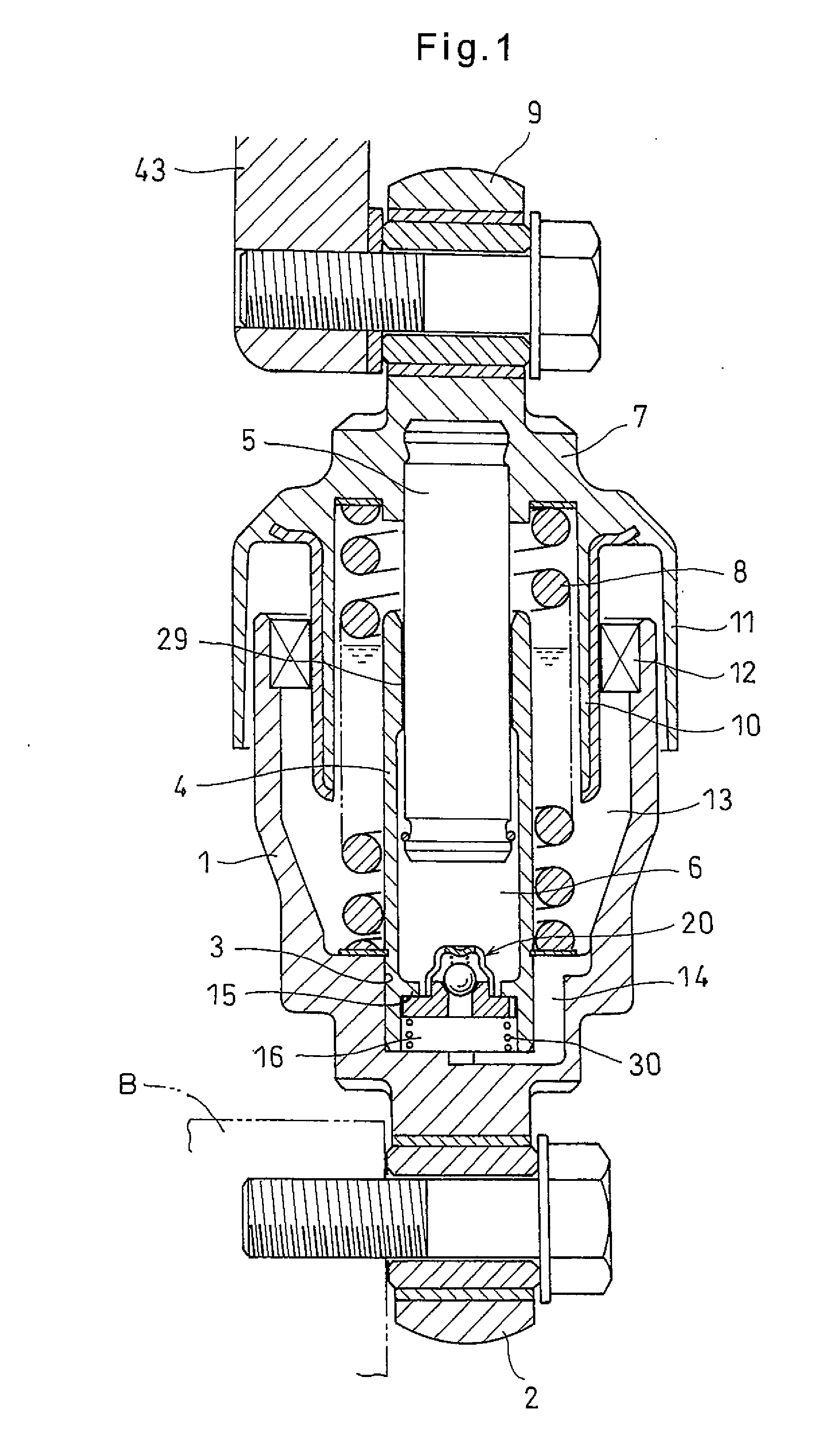
[0032]Now referring to the drawings, the auto-tensioner embodying the present invention includes, as shown in FIG. 1, a cylinder 1 having a closed bottom end formed with a coupling piece 2 rotatably coupled to an engine block.
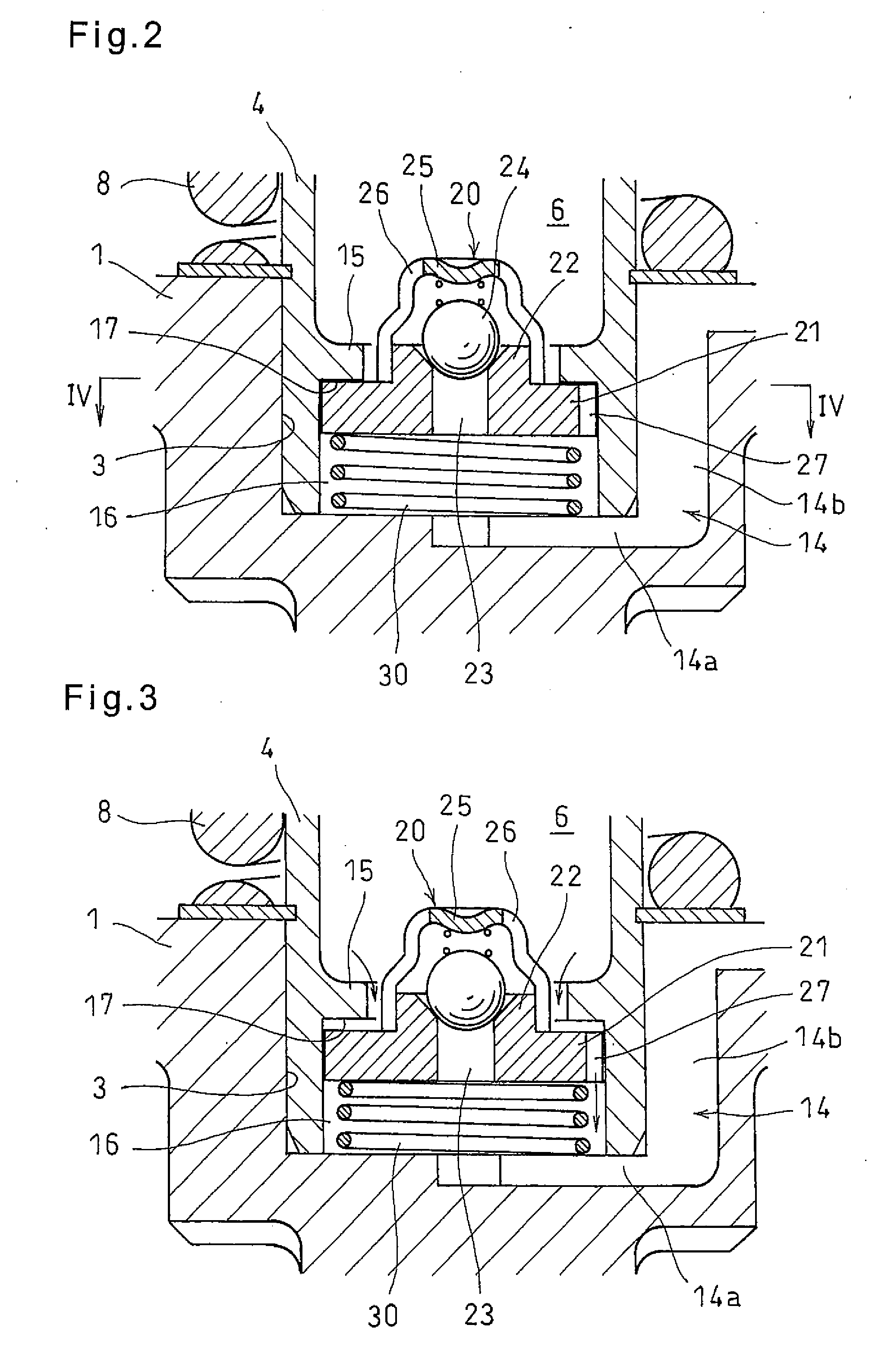
[0033]A sleeve fitting hole 3 having a smaller diameter than the inner diameter of the cylinder 1 is formed in the inner bottom surface of the cylinder 1. A sleeve 4 has its bottom end portion press-fitted in the sleeve fitting hole 3. A rod 5 has its lower portion slidably inserted in the sleeve 4, defining a pressure chamber 6 in the sleeve 4.
[0034]A spring seat 7 is fixed to the top end portion of the rod 5, which protrudes from the cylinder 1. A return spring 8 is mounted between the spring seat 7 and the inner bottom surface of the cylinder 1, biasing the cylinder 1 and the rod 5 in the direction in which the rod 5 protrudes from the cylinder 1.
[0035]The spring seat 7 has a coupling piece 9 at its top end which is configured to be coupled to the pulley arm...
PUM
 Abstract
Description
Claims
Application Information