Selective-Capacity Bodily Fluids Collection and Drainage Device

a technology of bodily fluids and devices, applied in gravity drainage systems, other nursing devices, medical science, etc., can solve the problems of user exposure to a high risk of infection, soiling of the user's clothing or restroom, and difficulty in changing bags

Inactive Publication Date: 2013-10-03
RACKLEY J DANIELL
View PDF16 Cites 7 Cited by
  • Summary
  • Abstract
  • Description
  • Claims
  • Application Information

AI Technical Summary

Benefits of technology

[0016]The common inlet valve consists of a common inflow tube, which connects via tubing to the catheter where bodily fluids, such as urine, will enter the selective capacity chamber. The inlet valve is characterized by a capacity-selector located below the common inflow tube. The capacity-selector can be positioned to allow bodily fluids to flow into one or all of the collection chambers via the divided inflow tube based on the collection capacity needed by the user. The capacity selector will allow the user to engage only one collection chamber, such as during more ambulatory daytime use, or to engage multiple collection chambers simultaneously, such as during nighttime use, without requiring the user to change from a smaller to larger bag. Furthermore, when the multi-chambered collection container remains in an unfolded position, the capacity selector will allow the user to switch from single-chambered use to multi-chambered use without having to adjust the collection chambers or remove or reposition the device, such as when the user unexpectedly finds that he or she is unable to empty a full single chamber.

Problems solved by technology

Using this same smaller bag at night, however, can be problematic as the bag quickly fills to capacity and the user's sleep must be repetitively interrupted so that the bag can be drained or the user risks infection from the overflow of urine itself, which can be colonized with bacteria.
Unfortunately, utilizing the present arrangement of two different bags requires the user to open the collection system in order to change bags at least once a day.
Significantly, each time the system is opened, the user is exposed to a high risk of infection.
Moreover, urine continues to flow from the catheter when a bag is disconnected, which can easily result in the soiling of the user's clothing or restroom.
Additionally, for elderly users, or those with other physical or cognitive impairments, the physical task of changing bags can be difficult or even painful.
Furthermore, there is no way to accomplish a change of bags discretely or in an impromptu situation, such as when the user is in public, or is in an unexpectedly prolonged business meeting, and finds him or herself with a filled smaller bag but without the means or time to get to a bathroom to empty it.
Even utilizing a larger bag during the day to avoid such an embarrassing situation is impractical and problematic in and of itself.
First, if the larger bag is only being employed as a day bag, the excess portion must be folded up and behind the top portion.
This can lead to embarrassing bulges when gravity or pressure causes fluid to seep up under the fold into the back portion of the bag.
Moreover, as the bottom of the bag bulges, pressure on the straps holding the bag to the leg or waist of the user will increase, which can lead to decreased circulation in the user's leg or waist.
Second, once in the folded position, the bag cannot be unfolded to allow for more comfortable and discreet containment unless the user first disrobes, unstraps the bag from his or her body, and then unfolds the bag.
Thus, there is no discrete way to achieve larger containment capacity from the folded position in an emergency situation.

Method used


Image

  • Selective-Capacity Bodily Fluids Collection and Drainage Device
  • Selective-Capacity Bodily Fluids Collection and Drainage Device
  • Selective-Capacity Bodily Fluids Collection and Drainage Device

Examples


Embodiment Construction

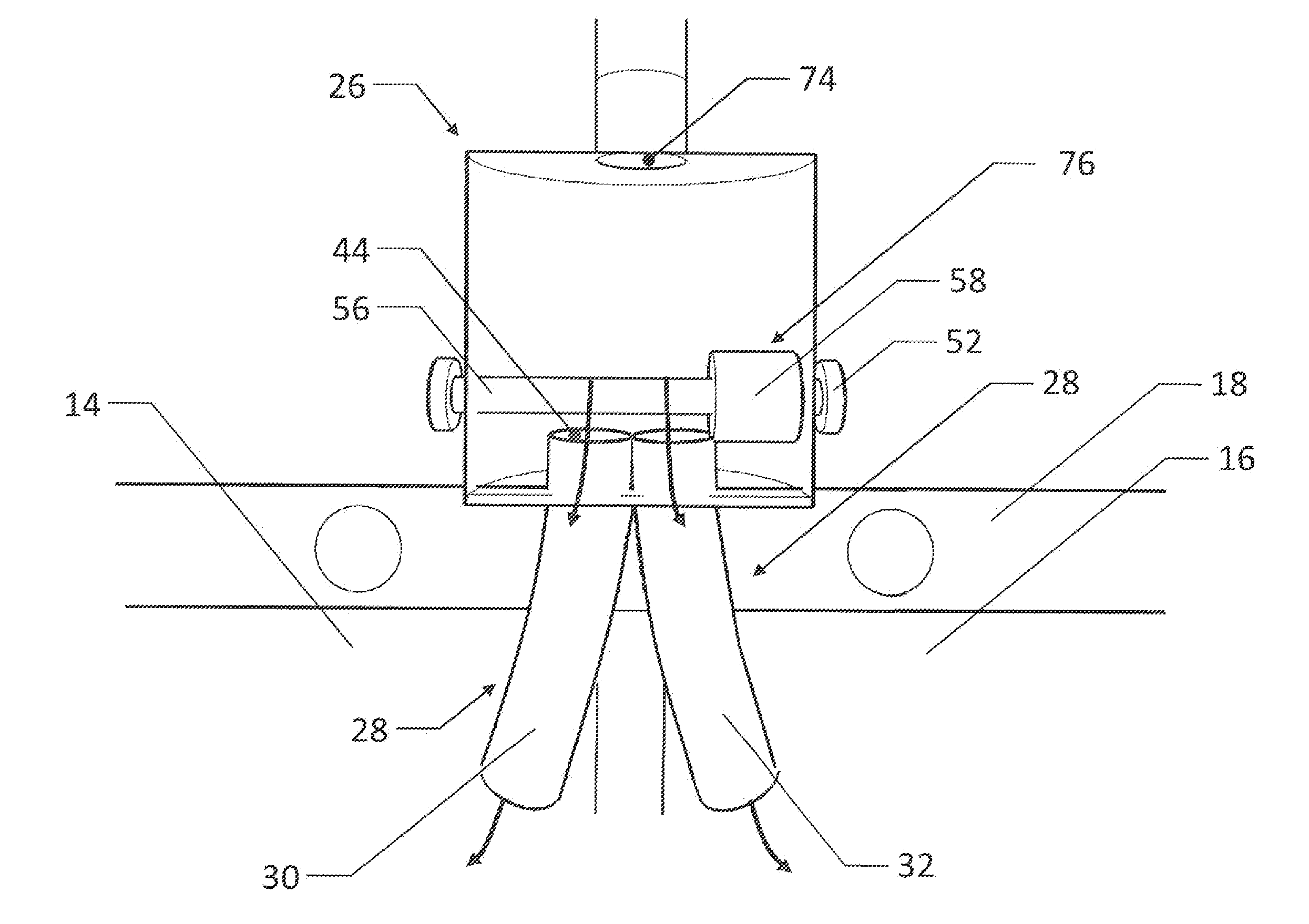
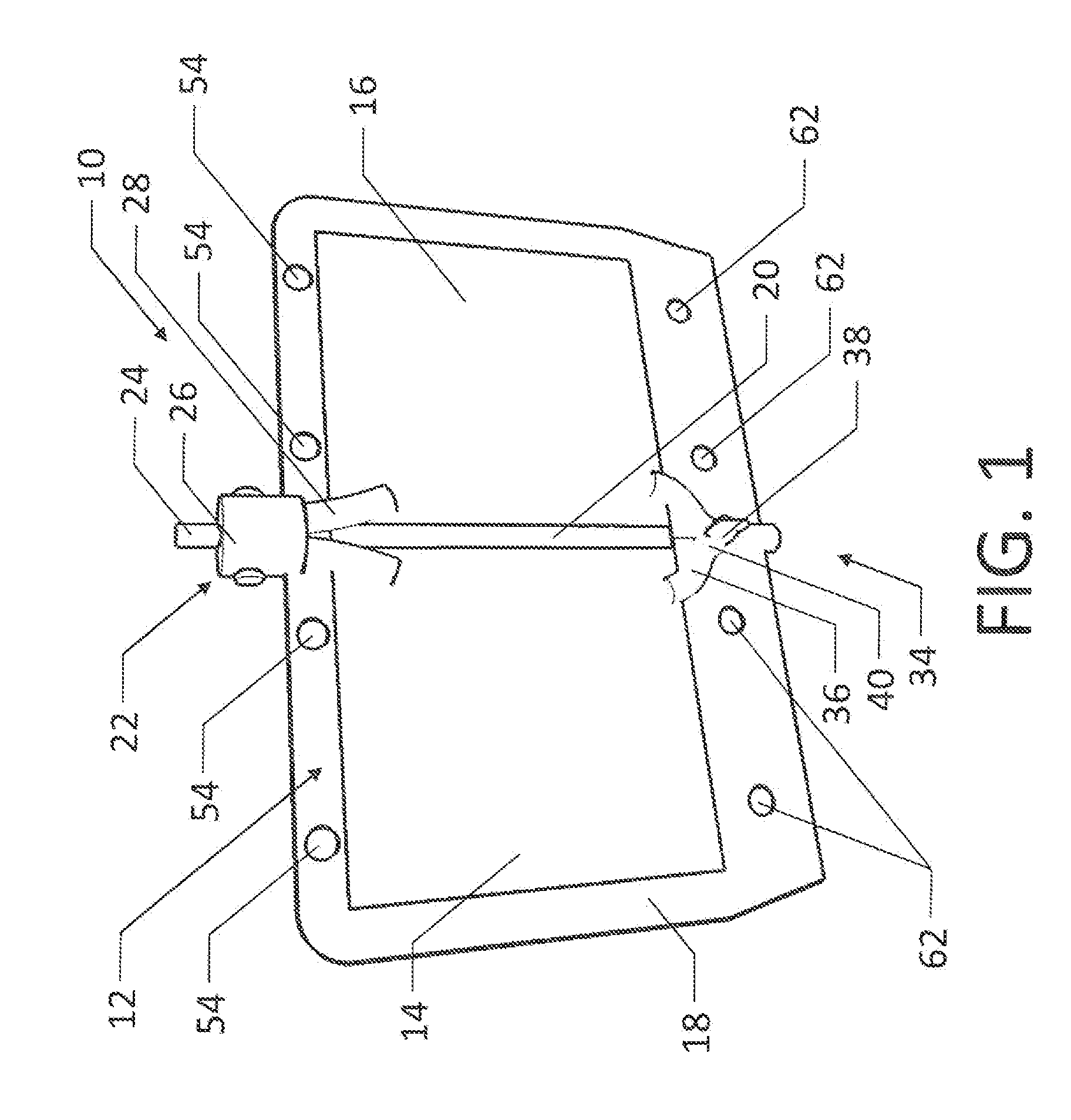
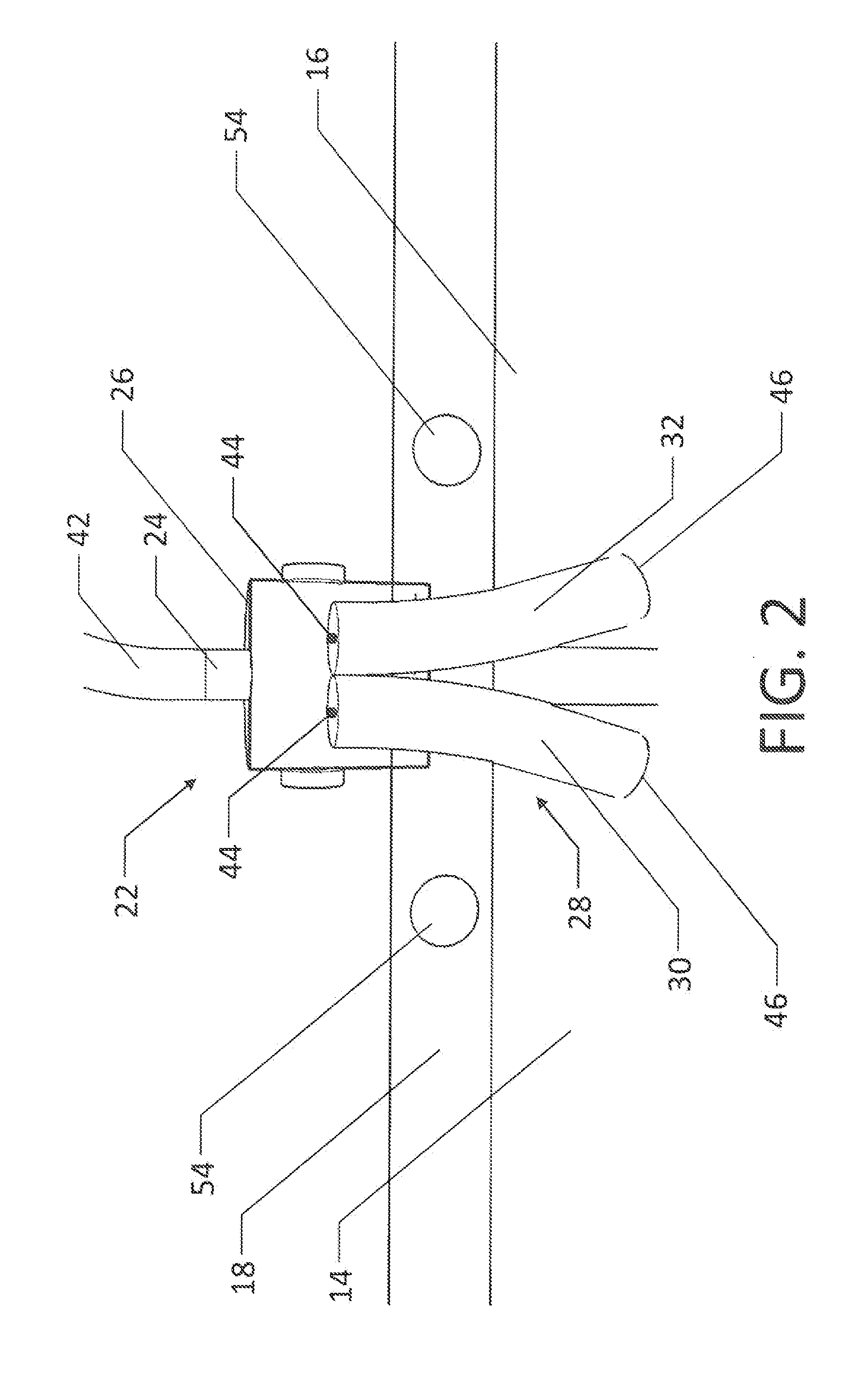
[0033]FIG. 1 illustrates the present invention in the preferred embodiment. The collection and drainage device 10 is generally made up of multi-chambered collection container 12, common inlet chamber 22, and common outlet chamber 34. Multi-chambered collection container 12, common inlet chamber 22, and common outlet chamber 34 are housed in outer casing 18.

[0034]Multi-chambered collection container 12 generally comprises two collection chambers, first collection chamber 14 and second collection chamber 16, in the preferred embodiment. However, multi-chambered collection container 12 can comprise more than two collection chambers. First collection chamber 14 and second collection chamber 16 can be made up of any flexible material that is impervious to bodily fluids, such as plastic, and is capable of lying flat when empty, as shown in FIG. 1, and expanding when filled, as shown in FIG. 10 and FIG. 11. Returning to FIG. 1, first collection chamber 14 and second collection chamber 16 a...


PUM


Abstract

A selective-capacity collection and drainage device having a first collection container, a second collection chamber and a common inlet valve characterized by a capacity selector and a common outlet valve connecting to each collection chamber. The common inlet valve consists of a common inflow tube, which connects via tubing to the catheter where bodily fluids will enter the selective capacity chamber. The inlet valve has a capacity-selector located between the common inflow tube and the multi-chambered container, such that bodily fluids are directed by the capacity-selector into one or all of the collection chambers via the divided inflow tube. Each individual chamber of the multi-chambered container is connected at its base to the common outlet valve. The common outlet valve consists of a divided outflow tube on top, which connects to each collection chamber, and converges at an outflow valve.

Description

CROSS-REFERENCES TO RELATED APPLICATIONS[0001]Not ApplicableSTATEMENT REGARDING FEDERALLY SPONSORED RESEARCH OR DEVELOPMENT[0002]Not ApplicableMICROFICHE APPENDIX[0003]Not ApplicableBACKGROUND OF THE INVENTION[0004]1. Field of the Invention[0005]This invention relates to the field of devices made for collection and drainage of bodily fluids, particularly urine. More specifically, the invention comprises two separate but adjoined collection chambers with a common outflow tube and a capacity selector that can be positioned to allow inflow of bodily fluids into one or both chambers, such that the device can be used for both smaller volume collection during ambulatory daytime use as well as for larger volume nighttime collection.[0006]2. Description of the Related Art[0007]When a person's natural ability to expel bodily fluids becomes impaired, such as with postoperative patients or those who have neurogenic bladders or benign prostatic enlargement, in many cases an artificial collectio...

Claims


Application Information

Patent Timeline
Patent Type & Authority Applications(United States)
IPC IPC(8): A61F5/44
CPCA61F5/4405A61F5/44A61M25/002A61F5/4408A61F5/48A61M25/0017A61F5/4407A61F2005/4402A61M1/0021A61M39/223A61F5/4404A61M39/22A61M1/70
Inventor RACKLEY, J. DANIELL
Owner RACKLEY J DANIELL
Why Eureka
Try Eureka