
Apparatus and method for automatically controlling a transmission of a wheel loader

a technology of automatic control and transmission, which is applied in the direction of mechanical equipment, instruments, transportation and packaging, etc., can solve the problems of deteriorating whole work efficiency and the time point at which the transmission operation of the wheel loader is actually performed

Inactive Publication Date: 2013-10-03
DOOSAN INFRACORE CO LTD
View PDF2 Cites 12 Cited by
  • Summary
  • Abstract
  • Description
  • Claims
  • Application Information

AI Technical Summary

Benefits of technology

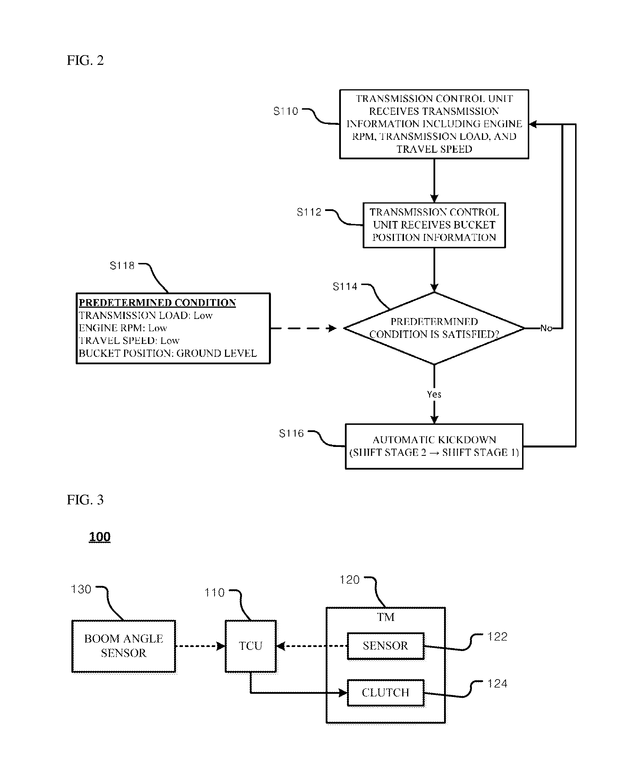
The present patent aims to provide an apparatus and method of automatically controlling a transmission in a wheel loader. The invention can remove time gaps between starting an operation such as excavation and performing the kickdown, increasing work efficiency. The invention can also allow for a kickdown transmission to be performed sooner than the starting of the operation, based on various conditions such as slow travel speed or a position or posture of the bucket. The invention provides a safe wheel loader that ensures the kickdown transmission does not occur in specific situations such as loading.

Problems solved by technology

However, in a case in which a transmission operation is performed by detecting an increase in transmission load during the operation such as excavation, a time point when the transmission operation of the wheel loader is actually performed is delayed from a time point when the excavation operation starts.
Therefore, because the transmission operation is performed during the excavation operation, an operator experiences difficulty that the whole work efficiency deteriorates.

Method used


Image

  • Apparatus and method for automatically controlling a transmission of a wheel loader
  • Apparatus and method for automatically controlling a transmission of a wheel loader
  • Apparatus and method for automatically controlling a transmission of a wheel loader

Examples


Embodiment Construction

[0027]Hereinafter, preferable exemplary embodiments of an aspect of the present disclosure will be described with reference to the drawings.

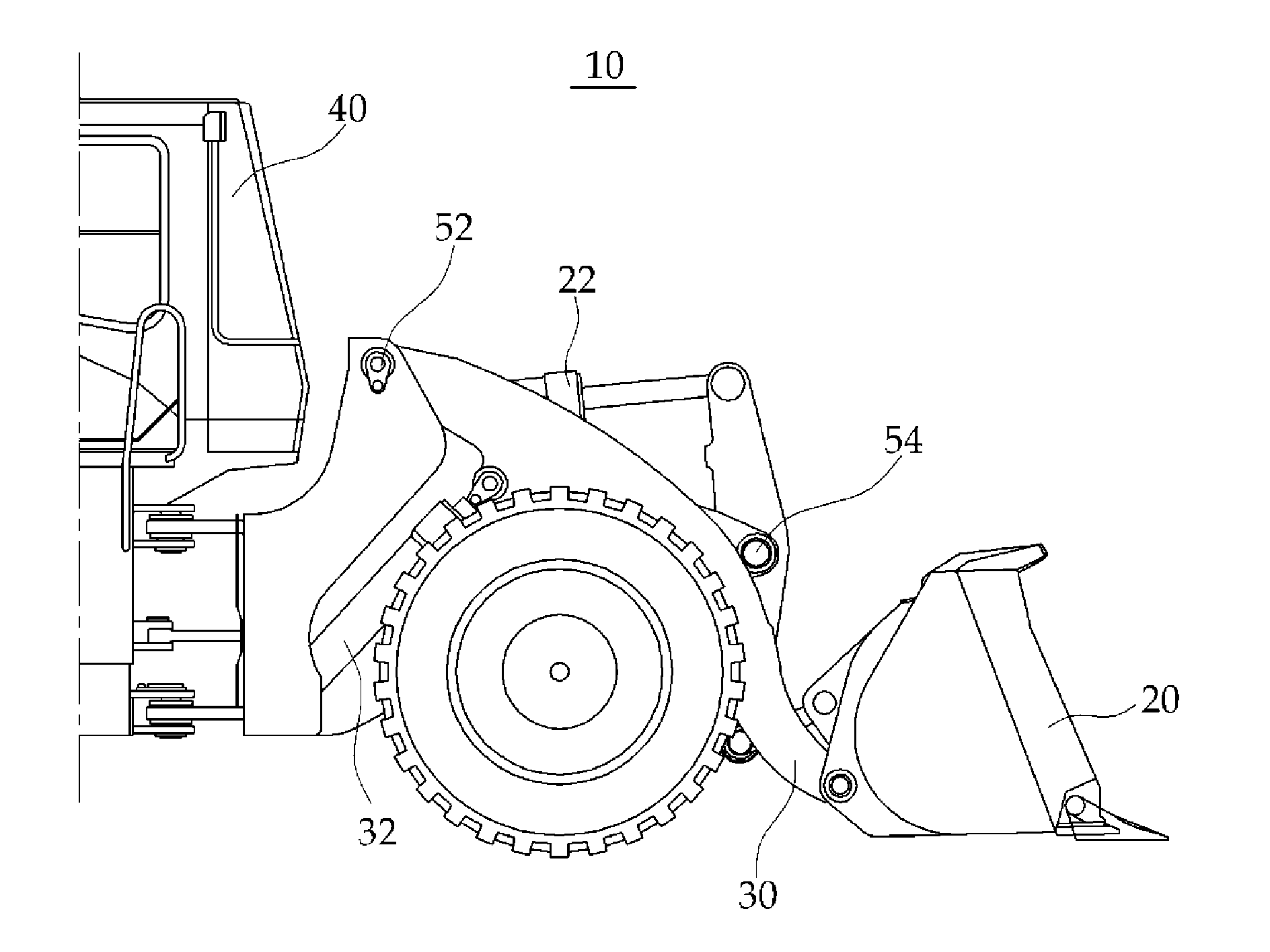
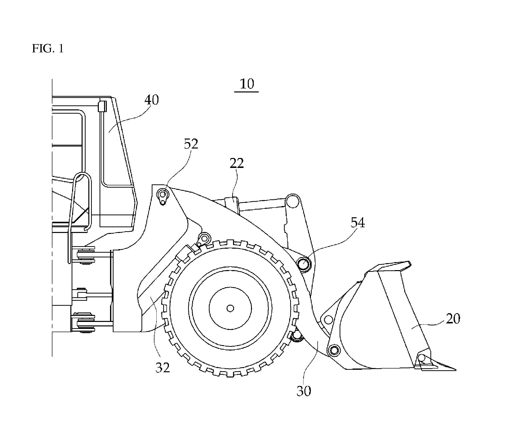
[0028]FIG. 1 is a schematic view illustrating a wheel loader 10 based on a front side where a bucket 20 is provided. Referring to FIG. 1, the wheel loader 10 includes the bucket 20 disposed at a front side of a vehicle, a boom 30 for supporting the bucket, and a driving means such as a bucket cylinder 22 and a boom cylinder 32 for driving the bucket 20 and the boom 30. In addition, the wheel loader 10 includes a cockpit 40 where an operator may be seated.

[0029]The wheel loader 10 having the configuration includes a boom angle sensor 52 and a bucket angle sensor 54 in accordance with characteristics of an aspect of the present disclosure. The sensors 52 and 54, for example, detects a position (a height) of the bucket 20 by detecting an angle of the boom 30 that is rotated by an operation of the boom cylinder 32, and may detect a posture of the bu...


PUM


Abstract

An aspect of the present disclosure has been made in an effort to provide an apparatus and a method of automatically controlling a transmission, capable of increasing work efficiency by removing a time gap between a starting time point when an operation such as excavation of a wheel loader starts and a transmission time point when the kickdown is performed. In addition, an aspect of the present disclosure has been made in an effort to provide an apparatus and a method of automatically controlling a transmission, capable of performing an automatic kickdown transmission at the same time of the starting time point of operation, preferably before the operation is performed.

Description

CROSS-REFERENCE TO RELATED APPLICATION[0001]This Application is a Section 371 National Stage Application of International Application No. PCT / KR2011 / 010126, filed Dec. 26, 2011 and published, not in English, as WO2012 / 087086 on Jun. 28, 2012.FIELD OF THE DISCLOSURE[0002]An aspect of the present disclosure relates to an apparatus and a method for automatically controlling a transmission of a wheel loader, and more particularly, to an automatic control method for allowing a kickdown to be automatically performed in a specific stage among a plurality of operational stages in which the wheel loader performs operations.BACKGROUND OF THE DISCLOSURE[0003]A wheel loader is used in construction, and widely used to perform an excavation operation for excavating soil, sand or the like, a conveyance operation for conveying the excavated soil and sand, loading and unloading operations of loading and unloading the conveyed soil and sand to and from a freight vehicle, soil preparation for road con...

Claims


Application Information

Patent Timeline
Patent Type & Authority Applications(United States)
IPC IPC(8): B60W10/11B60W10/30
CPCE02F9/2079E02F9/265B60W10/30B60W10/11B60K23/00F16H59/20F16H59/44F16H61/0213F16H2061/0244F16H59/14F16H59/66F16H59/16
Inventor JANG, IN PYO
Owner DOOSAN INFRACORE CO LTD
Learn More