Method and system for controlling aircraft braking on a runway

a technology for landing runways and aircraft, applied in the direction of automatic braking sequences, aircraft braking arrangements, instruments, etc., can solve the problems of inability to ensure the homogeneous state of the runway, high cost and time consumption of measuring braking performance on all runway states,

Active Publication Date: 2013-10-03
AIRBUS SAS +1
View PDF1 Cites 14 Cited by
  • Summary
  • Abstract
  • Description
  • Claims
  • Application Information

AI Technical Summary

Benefits of technology

[0011]The method, as one of its advantages, allows the simulation of the braking of the aircraft on a landing runway having a runway state for which the adhesion of the wheels of the aircraft to the landing runway is lower than the adhesion of the wheels of the aircraft to the landing runway actually used. It is thus possible to verify what the behaviour of the aircraft and of some of its systems would be on a landing runway whose state corresponds to the selected dummy runway state. Thus, by using one and the same landing runway having a current state corresponding to the highest adhesion of the wheels of the aircraft to the runway (“dry runway” state), it is possible to simulate the landing of the aircraft on a landing runway having any runway state (wet runway, presence of snow or ice, etc.). This avoids having to take the aircraft to another geographical location to carry out the desired braking trials, thereby saving time and cost.
[0045]In another embodiment, steps b) and c) are repeated in an iterative manner during the braking of the aircraft. This makes it possible to slave the actual braking of the aircraft to a deceleration set point computed in real time during at least one part of the aircraft braking phase, so as to simulate braking on a landing runway whose state corresponds to the dummy runway state selected in step a).
[0047]a selection means, e.g., a software unit, making it possible to select a dummy runway state for which the adhesion of the wheels of the aircraft to the landing runway is lower, over the whole of the speed range of the aircraft during this braking, than the adhesion of the wheels of the aircraft to the landing runway corresponding to the current runway state;

Problems solved by technology

To measure braking performance on all runway states would be expensive and time consuming, especially as compared to measuring braking performance on only dry and wet runway states.
Moreover, one cannot be certain that the state of the runway would be homogeneous over the whole of the length of the landing runway.

Method used


Image

  • Method and system for controlling aircraft braking on a runway
  • Method and system for controlling aircraft braking on a runway
  • Method and system for controlling aircraft braking on a runway

Examples


Embodiment Construction

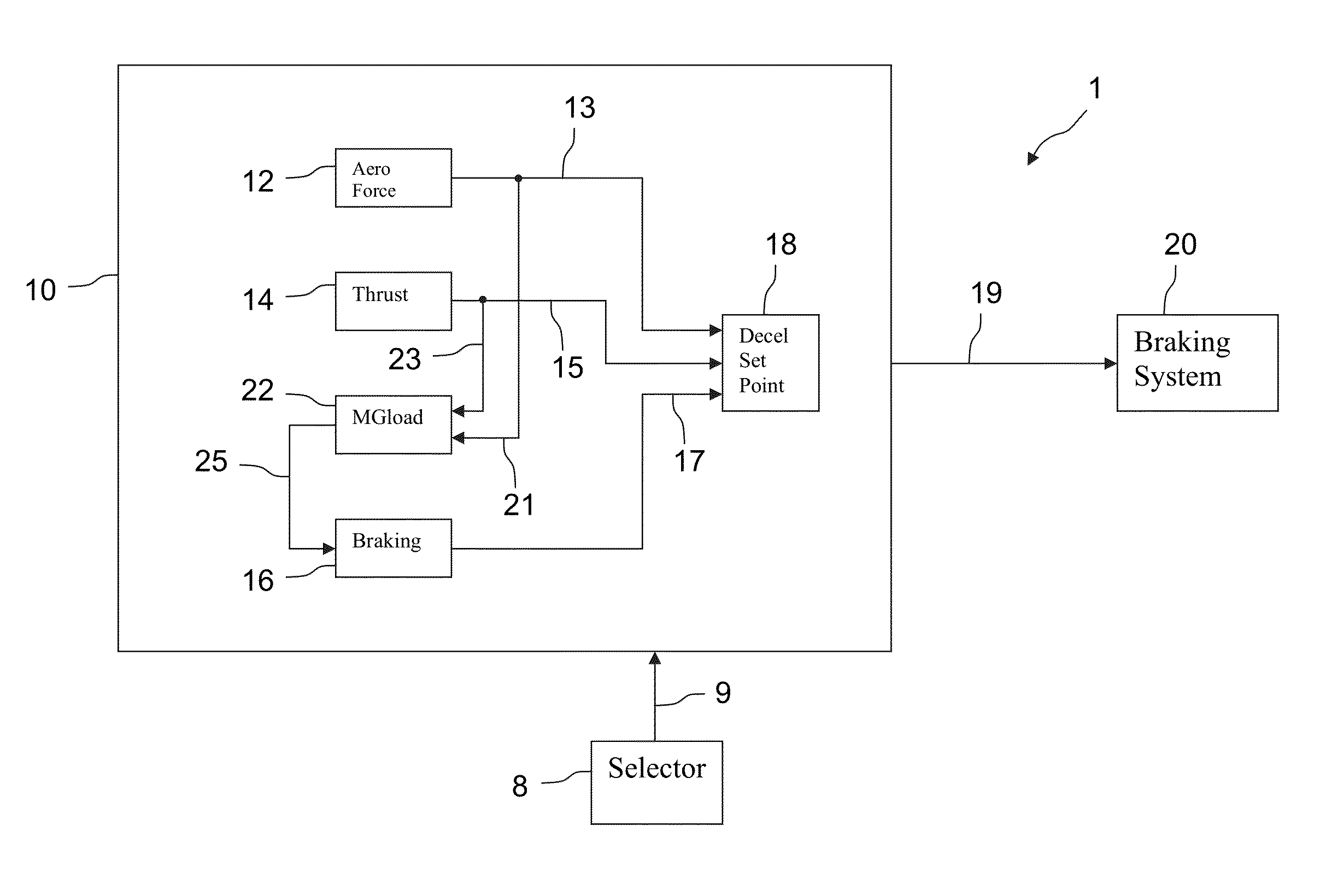
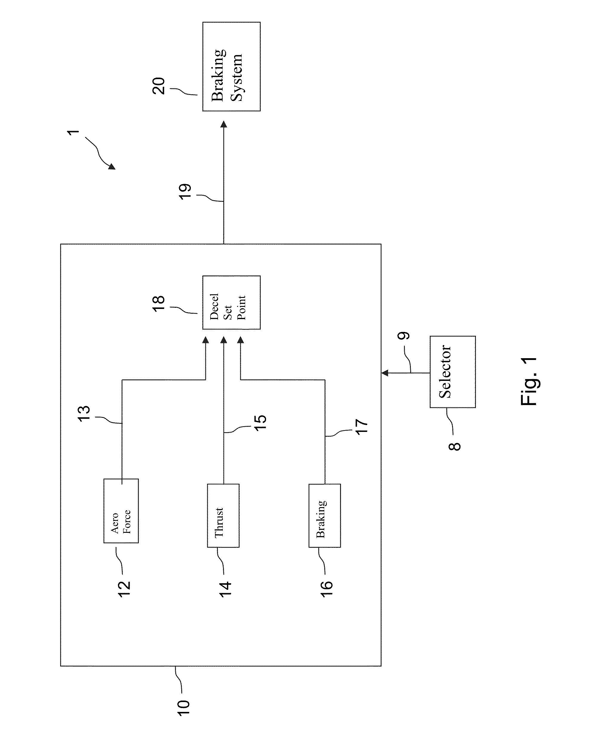
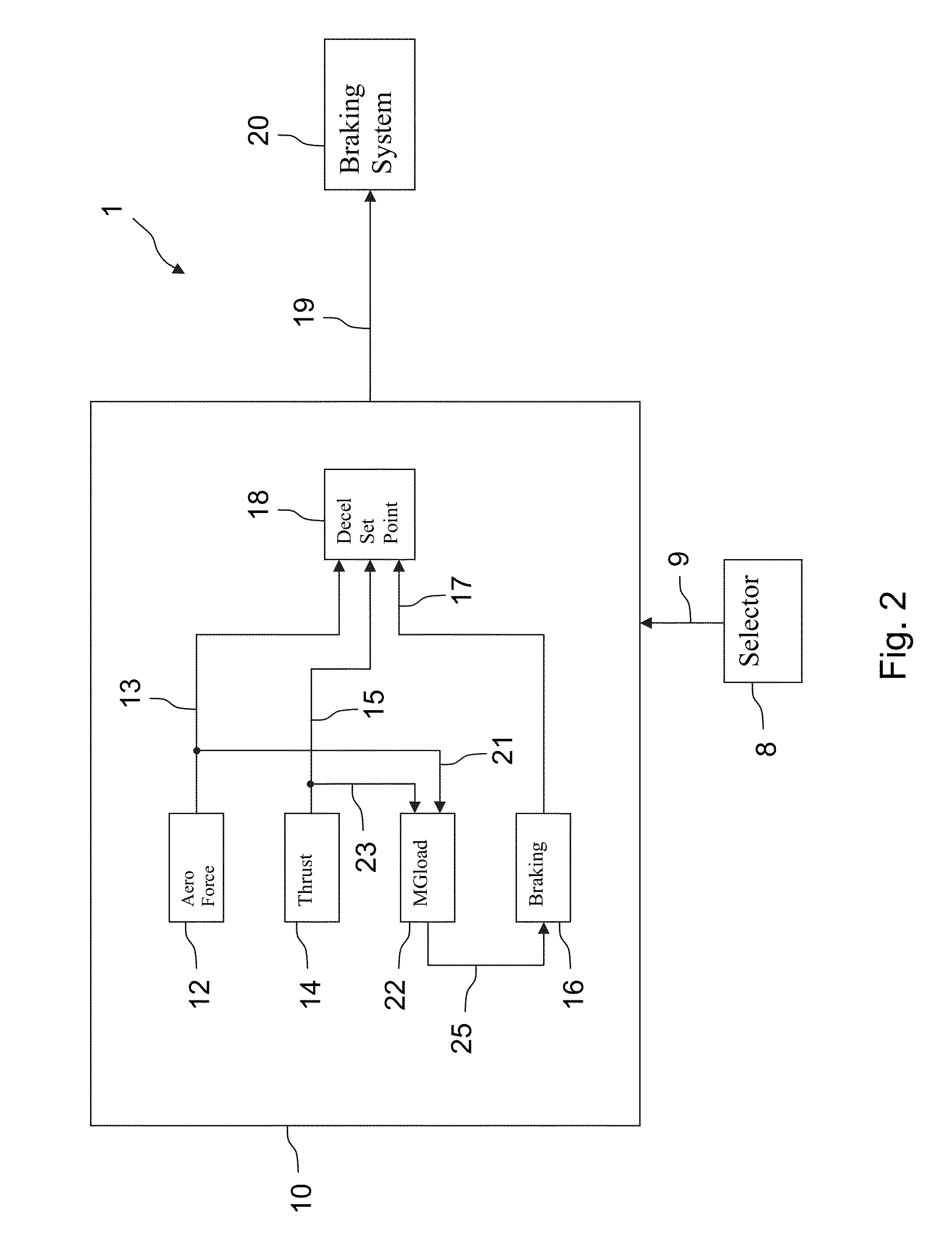
[0056]FIG. 1 illustrates a computer system 1 for controlling the braking of an aircraft. The system 1 may be an aircraft onboard system and in communication with and potentially control a braking system 20 of an aircraft. The device may include a deceleration computation means 10, and selection means 8 allowing a pilot or a crew member to select a dummy runway state for which he desires to simulate braking of the aircraft. These selection means is connected by a communications link 9 to the deceleration computation means 10.

[0057]When a pilot selects a dummy runway state by virtue of the selection means 8, the selected dummy runway sate is transmitted to the deceleration computation means 10, through the communications link 9. The deceleration computation means 10 may comprise a first means 12 for computing at least one aerodynamic force applied to the aircraft, a second means 14 for computing the thrust of the engines of the aircraft, a third means 16 for computing the braking forc...


PUM


Abstract

A method to control braking of an aircraft on a landing runway including: selecting a dummy runway state corresponding to a level of adhesion of wheels of the aircraft to a runway which is lower, over an entire speed range of the aircraft while braking on a runway, than an adhesion level of the wheels of the aircraft to the landing runway; calculating a set point of a deceleration value for the aircraft on the landing runway based on the landing runway for the selected dummy runway state, wherein the calculated set point corresponds to maximum braking value of the aircraft, and controlling the braking of the aircraft using the set point.

Description

RELATED APPLICATION[0001]This application claims priority to French Application 12-52921 filed on Mar. 30, 2012, the entirety of which is incorporated by reference.BACKGROUND[0002]The present invention relates to the field of the landing of aircraft on a landing runway.[0003]The effectiveness of aircraft braking on the landing runway depends on the state of the runway. The state of the landing runway depends on meteorological conditions. Examples of runway states include: dry, wet (rain), snow and ice.[0004]Patent application FR2.930.669 discloses a device onboard an aircraft for identifying the state of a landing runway on which this aircraft is landing.[0005]During trials of a new aircraft, the aircraft's braking performance is generally tested by landing the aircraft on runways under different runway states, such as a “dry runway” and a “wet runway.” The tests are used to create models of the aircraft's braking performance for different runway states. The braking performance of t...

Claims


Application Information

Patent Timeline
Patent Type & Authority Applications(United States)
IPC IPC(8): B64C25/42
CPCB64C25/426B60T8/1703
Inventor PICAUT, STEPHANEJOURNADE, JEROMEMORIN, REMILIGNEE, ROBERT
Owner AIRBUS SAS
Why Eureka
Try Eureka